STEERING PAD SWITCH INSPECTION
PROCEDURE
-
INSPECT STEERING PAD SWITCH ASSEMBLY
-
Inspect the steering pad switch assembly. (Type A)
-
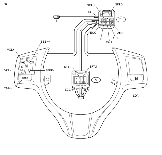
Measure the resistance according to the value(s) in the table below.
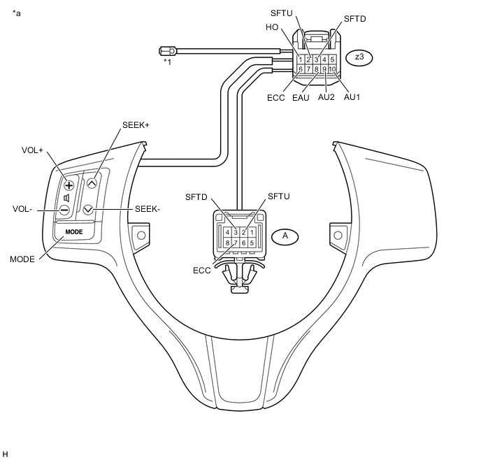
Text in Illustration *1 Terminal B - - *a Component without harness connected
(Steering Pad Switch Assembly)
- - Standard Resistance Tester Connection Switch Condition Specified Condition z3-1 (HO) - Terminal B Always Below 2.5 Ω z3-10 (AU1) - z3 - 8 (EAU) No switch pushed 95 to 105 kΩ z3-9 (AU2) - z3 - 8 (EAU) No switch pushed 95 to 105 kΩ z3-10 (AU1) - z3 - 8 (EAU) Volume+ switch: pushed 950 to 1050 Ω z3-9 (AU2) - z3-8 (EAU) Volume+ switch: pushed 95 to 105 kΩ z3-10 (AU1) - z3-8 (EAU) Volume- switch: pushed 2955 to 3265 Ω z3-9 (AU2) - z3-8 (EAU) Volume- switch: pushed 95 to 105 kΩ z3-10 (AU1) - z3-8 (EAU) Seek+ switch: pushed Below 2.5 Ω z3-9 (AU2) - z3-8 (EAU) Seek+ switch: pushed 95 to 105 kΩ z3-10 (AU1) - z3-8 (EAU) Seek- switch: pushed 313 to 345 Ω z3-9 (AU2) - z3-8 (EAU) Seek- switch: pushed 95 to 105 kΩ z3-10 (AU1) - z3-8 (EAU) Mode switch: pushed 95 to 105 kΩ z3-9 (AU2) - z3-8 (EAU) Mode switch: pushed Below 2.5 Ω z3-2 (SFTU) - A-2 (SFTU) Always Below 2.5 Ω z3-3 (SFTD) - A-3 (SFTD) Always Below 2.5 Ω z3-6 (ECC) - A-7 (ECC) Always Below 2.5 Ω If the result is not as specified, replace the steering pad switch assembly.
-
-
Inspect the steering pad switch assembly. (Type B)
-
Measure the resistance according to the value(s) in the table below.
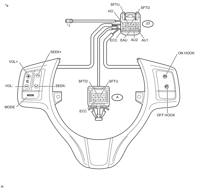
Text in Illustration *1 Terminal B - - *a Component without harness connected
(Steering Pad Switch Assembly)
- - Standard Resistance Tester Connection Switch Condition Specified Condition z3-1 (HO) - Terminal B Always Below 2.5 Ω z3-10 (AU1) - z3-8 (EAU) No switch pushed 95 to 105 kΩ z3-9 (AU2) - z3-8 (EAU) No switch pushed 95 to 105 kΩ z3-10 (AU1) - z3-8 (EAU) Volume+ switch: pushed 950 to 1050 Ω z3-9 (AU2) - z3-8 (EAU) Volume+ switch: pushed 95 to 105 kΩ z3-10 (AU1) - z3-8 (EAU) Volume- switch: pushed 2955 to 3265 Ω z3-9 (AU2) - z3-8 (EAU) Volume- switch: pushed 95 to 105 kΩ z3-10 (AU1) - z3-8 (EAU) Seek+ switch: pushed Below 2.5 Ω z3-9 (AU2) - z3-8 (EAU) Seek+ switch: pushed 95 to 105 kΩ z3-10 (AU1) - z3-8 (EAU) Seek- switch: pushed 313 to 345 Ω z3-9 (AU2) - z3-8 (EAU) Seek- switch: pushed 95 to 105 kΩ z3-10 (AU1) - z3-8 (EAU) On Hook switch: pushed 95 to 105 kΩ z3-9 (AU2) - z3-8 (EAU) On Hook switch: pushed 313 to 345 Ω z3-10 (AU1) - z3-8 (EAU) Off Hook switch: pushed 95 to 105 kΩ z3-9 (AU2) - z3-8 (EAU) Off Hook switch: pushed 950 to 1050 Ω z3-10 (AU1) - z3-8 (EAU) Mode switch: pushed 95 to 105 kΩ z3-9 (AU2) - z3-8 (EAU) Mode switch: pushed Below 2.5 Ω z3-2 (SFTU) - A-2 (SFTU) Always Below 2.5 Ω z3-3 (SFTD) - A-3 (SFTD) Always Below 2.5 Ω z3-6 (ECC) - A-7 (ECC) Always Below 2.5 Ω If the result is not as specified, replace the steering pad switch assembly.
-
-
Inspect the steering pad switch assembly. (Type C)
-
Measure the resistance according to the value(s) in the table below.
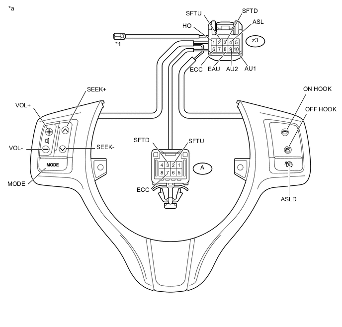
Text in Illustration *1 Terminal B - - *a Component without harness connected
(Steering Pad Switch Assembly)
- - Standard Resistance Tester Connection Switch Condition Specified Condition z3-1 (HO) - Terminal B Always Below 2.5 Ω z3-10 (AU1) - z3-8 (EAU) No switch pushed 95 to 105 kΩ z3-9 (AU2) - z3-8 (EAU) No switch pushed 95 to 105 kΩ z3-10 (AU1) - z3-8 (EAU) Volume+ switch: pushed 950 to 1050 Ω z3-9 (AU2) - z3-8 (EAU) Volume+ switch: pushed 95 to 105 kΩ z3-10 (AU1) - z3-8 (EAU) Volume- switch: pushed 2955 to 3265 Ω z3-9 (AU2) - z3-8 (EAU) Volume- switch: pushed 95 to 105 kΩ z3-10 (AU1) - z3-8 (EAU) Seek+ switch: pushed Below 2.5 Ω z3-9 (AU2) - z3-8 (EAU) Seek+ switch: pushed 95 to 105 kΩ z3-10 (AU1) - z3-8 (EAU) Seek- switch: pushed 313 to 345 Ω z3-9 (AU2) - z3-8 (EAU) Seek- switch: pushed 95 to 105 kΩ z3-10 (AU1) - z3-8 (EAU) On Hook switch: pushed 95 to 105 kΩ z3-9 (AU2) - z3-8 (EAU) On Hook switch: pushed 313 to 345 Ω z3-10 (AU1) - z3-8 (EAU) Off Hook switch: pushed 95 to 105 kΩ z3-9 (AU2) - z3-8 (EAU) Off Hook switch: pushed 950 to 1050 Ω z3-10 (AU1) - z3-8 (EAU) Mode switch: pushed 95 to 105 kΩ z3-9 (AU2) - z3-8 (EAU) Mode switch: pushed Below 2.5 Ω z3-10 (AU1) - z3-8 (EAU) ASLD switch: pushed 95 to 105 kΩ z3-9 (AU2) - z3-8 (EAU) ASLD switch: pushed 95 to 105 kΩ z3-4 (ASL) - z3-6 (ECC) ASLD switch: pushed Below 2.5 Ω z3-2 (SFTU) - A-2 (SFTU) Always Below 2.5 Ω z3-3 (SFTD) - A-3 (SFTD) Always Below 2.5 Ω z3-6 (ECC) - A-7 (ECC) Always Below 2.5 Ω If the result is not as specified, replace the steering pad switch assembly.
-
-
Inspect the steering pad switch assembly. (Type D)
-
Measure the resistance according to the value(s) in the table below.
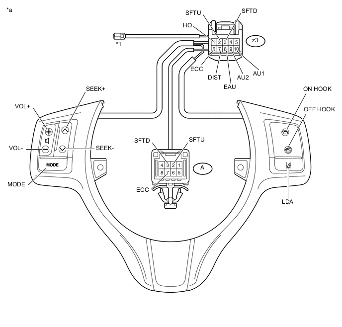
Text in Illustration *1 Terminal B - - *a Component without harness connected
(Steering Pad Switch Assembly)
- - Standard Resistance Tester Connection Switch Condition Specified Condition z3-1 (HO) - Terminal B Always Below 2.5 Ω z3-10 (AU1) - z3-8 (EAU) No switch pushed 95 to 105 kΩ z3-9 (AU2) - z3-8 (EAU) No switch pushed 95 to 105 kΩ z3-10 (AU1) - z3-8 (EAU) Volume+ switch: pushed 950 to 1050 Ω z3-9 (AU2) - z3-8 (EAU) Volume+ switch: pushed 95 to 105 kΩ z3-10 (AU1) - z3-8 (EAU) Volume- switch: pushed 2955 to 3265 Ω z3-9 (AU2) - z3-8 (EAU) Volume- switch: pushed 95 to 105 kΩ z3-10 (AU1) - z3-8 (EAU) Seek+ switch: pushed Below 2.5 Ω z3-9 (AU2) - z3-8 (EAU) Seek+ switch: pushed 95 to 105 kΩ z3-10 (AU1) - z3-8 (EAU) Seek- switch: pushed 313 to 345 Ω z3-9 (AU2) - z3-8 (EAU) Seek- switch: pushed 95 to 105 kΩ z3-10 (AU1) - z3-8 (EAU) On Hook switch: pushed 95 to 105 kΩ z3-9 (AU2) - z3-8 (EAU) On Hook switch: pushed 313 to 345 Ω z3-10 (AU1) - z3-8 (EAU) Off Hook switch: pushed 95 to 105 kΩ z3-9 (AU2) - z3-8 (EAU) Off Hook switch: pushed 950 to 1050 Ω z3-10 (AU1) - z3-8 (EAU) Mode switch: pushed 95 to 105 kΩ z3-9 (AU2) - z3-8 (EAU) Mode switch: pushed Below 2.5 Ω z3-10 (AU1) - z3-8 (EAU) LDA switch: pushed 95 to 105 kΩ z3-9 (AU2) - z3-8 (EAU) LDA switch: pushed 95 to 105 kΩ z3-7 (DIST) - z3-7 (ECC) LDA switch: pushed 228 to 252 Ω z3-2 (SFTU) - A-2 (SFTU) Always Below 2.5 Ω z3-3 (SFTD) - A-3 (SFTD) Always Below 2.5 Ω z3-6 (ECC) - A-7 (ECC) Always Below 2.5 Ω If the result is not as specified, replace the steering pad switch assembly.
-
-
Inspect the steering pad switch assembly. (Type E)
-
Measure the resistance according to the value(s) in the table below.
Text in Illustration *1 Terminal B - - *a Component without harness connected
(Steering Pad Switch Assembly)
- - Standard Resistance Tester Connection Switch Condition Specified Condition z3-1 (HO) - Terminal B Always Below 2.5 Ω z3-10 (AU1) - z3-8 (EAU) No switch pushed 95 to 105 kΩ z3-9 (AU2) - z3-8 (EAU) No switch pushed 95 to 105 kΩ z3-10 (AU1) - z3-8 (EAU) Volume+ switch: pushed 950 to 1050 Ω z3-9 (AU2) - z3-8 (EAU) Volume+ switch: pushed 95 to 105 kΩ z3-10 (AU1) - z3-8 (EAU) Volume- switch: pushed 2955 to 3265 Ω z3-9 (AU2) - z3-8 (EAU) Volume- switch: pushed 95 to 105 kΩ z3-10 (AU1) - z3-8 (EAU) Seek+ switch: pushed Below 2.5 Ω z3-9 (AU2) - z3-8 (EAU) Seek+ switch: pushed 95 to 105 kΩ z3-10 (AU1) - z3-8 (EAU) Seek- switch: pushed 313 to 345 Ω z3-9 (AU2) - z3-8 (EAU) Seek- switch: pushed 95 to 105 kΩ z3-10 (AU1) - z3-8 (EAU) Mode switch: pushed 95 to 105 kΩ z3-9 (AU2) - z3-8 (EAU) Mode switch: pushed Below 2.5 Ω z3-10 (AU1) - z3-8 (EAU) LDA switch: pushed 95 to 105 kΩ z3-9 (AU2) - z3-8 (EAU) LDA switch: pushed 95 to 105 kΩ z3-7 (DIST) - z3-6 (ECC) LDA switch: pushed 228 to 252 Ω z3-2 (SFTU) - A-2 (SFTU) Always Below 2.5 Ω z3-3 (SFTD) - A-3 (SFTD) Always Below 2.5 Ω z3-6 (ECC) - A-7 (ECC) Always Below 2.5 Ω If the result is not as specified, replace the steering pad switch assembly.
-
-
Inspect the steering pad switch assembly. (Type F)
-
Measure the resistance according to the value(s) in the table below.

Text in Illustration *1 Terminal B - - *a Component without harness connected
(Steering Pad Switch Assembly)
- - Standard Resistance Tester Connection Switch Condition Specified Condition z3-1 (HO) - Terminal B Always Below 2.5 Ω z3-10 (AU1) - z3-8 (EAU) No switch pushed 95 to 105 kΩ z3-9 (AU2) - z3-8 (EAU) No switch pushed 95 to 105 kΩ z3-10 (AU1) - z3-8 (EAU) Volume+ switch: pushed 950 to 1050 Ω z3-9 (AU2) - z3-8 (EAU) Volume+ switch: pushed 95 to 105 kΩ z3-10 (AU1) - z3-8 (EAU) Volume- switch: pushed 2955 to 3265 Ω z3-9 (AU2) - z3-8 (EAU) Volume- switch: pushed 95 to 105 kΩ z3-10 (AU1) - z3-8 (EAU) Seek+ switch: pushed Below 2.5 Ω z3-9 (AU2) - z3-8 (EAU) Seek+ switch: pushed 95 to 105 kΩ z3-10 (AU1) - z3-8 (EAU) Seek- switch: pushed 313 to 345 Ω z3-9 (AU2) - z3-8 (EAU) Seek- switch: pushed 95 to 105 kΩ z3-10 (AU1) - z3-8 (EAU) On Hook switch: pushed 95 to 105 kΩ z3-9 (AU2) - z3-8 (EAU) On Hook switch: pushed 313 to 345 Ω z3-10 (AU1) - z3-8 (EAU) Off Hook switch: pushed 95 to 105 kΩ z3-9 (AU2) - z3-8 (EAU) Off Hook switch: pushed 950 to 1050 Ω z3-10 (AU1) - z3-8 (EAU) Mode switch: pushed 95 to 105 kΩ z3-9 (AU2) - z3-8 (EAU) Mode switch: pushed Below 2.5 Ω z3-10 (AU1) - z3-8 (EAU) ASLD switch: pushed 95 to 105 kΩ z3-9 (AU2) - z3-8 (EAU) ASLD switch: pushed 95 to 105 kΩ z3-4 (ASL) - z3-6 (ECC) ASLD switch: pushed Below 2.5 Ω z3-10 (AU1) - z3-8 (EAU) LDA switch: pushed 95 to 105 kΩ z3-9 (AU2) - z3-8 (EAU) LDA switch: pushed 95 to 105 kΩ z3-7 (DIST) - z3-6 (ECC) LDA switch: pushed 228 to 252 Ω z3-2 (SFTU) - A-2 (SFTU) Always Below 2.5 Ω z3-3 (SFTD) - A-3 (SFTD) Always Below 2.5 Ω z3-6 (ECC) - A-7 (ECC) Always Below 2.5 Ω If the result is not as specified, replace the steering pad switch assembly.
-
-