AUDIO AND VISUAL SYSTEM(for Radio and Display Type) Stereo Component Amplifier Power Source Circuit
DESCRIPTION
The power provides power to the stereo component amplifier assembly.
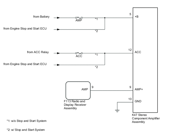
WIRING DIAGRAM
CAUTION / NOTICE / HINT
Note
Inspect the fuses for circuits related to this system before performing the following inspection procedure.
PROCEDURE
-
CHECK HARNESS AND CONNECTOR (STEREO COMPONENT AMPLIFIER ASSEMBLY- BATTERY AND BODY GROUND)
-
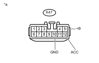
Text in Illustration *a Front view of wire harness connector
(to Stereo Component Amplifier Assembly)
Disconnect the stereo component amplifier assembly connector.
-
Measure the resistance according to the value(s) in the table below.
Standard Resistance Tester Connection Condition Specified Condition K47-10 (GND) - Body ground Always Below 1 Ω -
Measure the voltage according to the value(s) in the table below.
Standard Voltage Tester Connection Switch Condition Specified Condition K47-5 (+B) - Body ground Always 11 to 14 V K47-12 (ACC) - Body ground Ignition switch ACC 11 to 14 V
NG 
REPAIR OR REPLACE HARNESS OR CONNECTOR
OK 
-
-
CHECK HARNESS AND CONNECTOR (STEREO COMPONENT AMPLIFIER ASSEMBLY - RADIO AND DISPLAY RECEIVER ASSEMBLY)
-
Disconnect the K47 stereo component amplifier assembly connector.
-
Disconnect the F113 radio and display receiver assembly connector.
-
Measure the resistance according to the value(s) in the table below.
Standard Resistance Tester Connection Condition Specified Condition K47-9 (AMP+) - F113-9 (AMP) Always Below 1 Ω K47-9 (AMP+) - Body ground Always 10 kΩ or higher
OK
PROCEED TO NEXT SUSPECTED AREA SHOWN IN PROBLEM SYMPTOMS TABLE Click here
NG
REPAIR OR REPLACE HARNESS OR CONNECTOR
-