REAR AXLE BEAM INSTALLATION

PROCEDURE
-
INSTALL REAR AXLE CARRIER BUSH LH
-
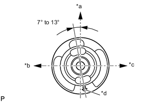
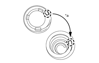
Text in Illustration *a Upper Side *b Front Side *c Rear Side *d Bush Mark Align the matchmarks on a new rear axle carrier bush LH and the rear axle beam assembly and provisionally install the rear axle carrier bush LH onto the rear axle beam assembly, as shown in the illustration.
Note
Install the new bush in the same orientation as the old one was prior to removal, because they are directional.
-
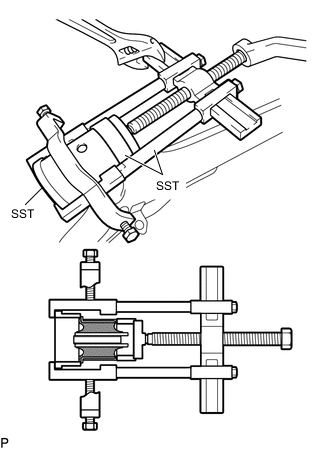
Using SST, install the rear axle carrier bush LH to the rear axle beam assembly.
- SST
- 09950-40011 ( 09951-04020, 09952-04010, 09953-04030, 09954-04030, 09955-04051, 09957-04010, 09958-04011 )
- 09950-60020 ( 09951-00810 )
- 09387-02010
- 09223-15020
Note
Do not damage the rubber portion when installing the rear axle carrier bush LH.
-
-
INSTALL REAR AXLE CARRIER BUSH RH
Tech Tips
Use the same procedure for the RH side as for the LH side.
-
TEMPORARILY TIGHTEN REAR AXLE BEAM ASSEMBLY
-
Slowly jack up the rear axle beam assembly using an engine lifter, 2 wooden blocks and 2 plate lift attachments or equivalent tools and temporarily install the rear axle beam assembly to the vehicle with the 2 bolts B.
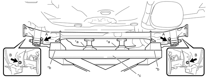
*a Plate Lift Attachment *b Wooden Block *c Engine Lifter - - Note
Make sure to secure the rear axle beam assembly to prevent it from dropping.
-
Temporarily install the rear axle beam assembly to the rear shock absorber assemblies LH and RH with the 2 bolts A and 2 nuts.
Note
Because the nut has its own stopper, do not turn the nut. Loosen the bolt with the nut fixed in place.
-
-
INSTALL REAR COIL SPRING
-
Support the spring seat of the rear axle beam assembly using an engine lifter and 2 wooden blocks.
-
Remove the 2 bolts and 2 nuts, and separate the rear axle beam assembly from the rear shock absorber assemblies LH and RH.
Note
Because the nut has its own stopper, do not turn the nut. Loosen the bolt with the nut fixed in place.
-
Slowly lower the rear axle beam assembly using engine lifter.
-
Install the rear coil spring lower insulator LH to the rear axle beam assembly.
-
*a Fit Install the rear coil spring upper insulator LH so that its gap fits to the end of the rear coil spring LH.
-
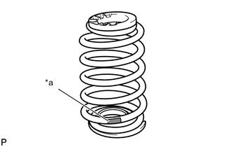
*a Paint Mark Install the rear coil spring LH to the rear axle beam assembly.
Note
The paint mark of the rear coil spring LH should be towards the underside and rear side of the vehicle.
-
Slowly jack up the rear axle beam assembly using engine lifter, and temporarily tighten the rear axle beam assembly to the rear shock absorber assemblies LH and RH with the 2 bolts and 2 nuts.
Note
Because the nut has its own stopper, do not turn the nut. Loosen the bolt with the nut fixed in place.
-
-
INSTALL FRONT FLOOR PANEL BRACE LH (for 2ZR-FE)
-
Install the front floor panel brace LH to the vehicle with the 3 bolts.
- Torque:
- 30.1 N*m { 307 kgf*cm, 22 ft.*lbf }
-
-
INSTALL FRONT FLOOR PANEL BRACE RH (for 2ZR-FE)
Tech Tips
Use the same procedure for the RH side as for the LH side.
-
INSTALL FRONT FLOOR CENTER BRACE (for 2ZR-FE)
-
Install the front floor center brace to the vehicle with the 4 bolts.
- Torque:
- 30.1 N*m { 307 kgf*cm, 22 ft.*lbf }
-
-
INSTALL REAR AXLE HUB AND BEARING ASSEMBLY (for Rear Drum Brake)
-
INSTALL REAR AXLE HUB AND BEARING ASSEMBLY (for Rear Disc Brake)
-
INSPECT REAR AXLE HUB BEARING BACKLASH (for Rear Drum Brake)
-
INSPECT REAR AXLE HUB BEARING BACKLASH (for Rear Disc Brake)
-
INSPECT REAR AXLE HUB RUNOUT (for Rear Drum Brake)
-
INSPECT REAR AXLE HUB RUNOUT (for Rear Disc Brake)
-
INSTALL REAR BRAKE DRUM SUB-ASSEMBLY (for Rear Drum Brake)
-
INSTALL REAR DISC (for Rear Disc Brake)
-
INSTALL REAR DISC BRAKE CALIPER ASSEMBLY LH (for Rear Disc Brake)
-
INSTALL REAR DISC BRAKE CALIPER ASSEMBLY RH (for Rear Disc Brake)
Tech Tips
Use the same procedure for the RH side as for the LH side.
-
INSTALL NO. 3 PARKING BRAKE CABLE ASSEMBLY
-
Install the No. 3 parking brake cable assembly with the bolt and a new clamp.
- Torque:
- 6.0 N*m { 61 kgf*cm, 53 in.*lbf }
-
-
INSTALL NO. 2 PARKING BRAKE CABLE ASSEMBLY
Tech Tips
Use the same procedure for the RH side as for the LH side.
-
INSTALL REAR NO. 4 BRAKE TUBE (for Rear Drum Brake)
-
Install the rear No. 4 brake tube to the rear axle beam assembly with the nut.
- Torque:
- 5.0 N*m { 51 kgf*cm, 44 in.*lbf }
-
Install the rear flexible hose LH to the rear axle beam assembly with a new clip.
-
Using a 10 mm union nut wrench, connect the rear No. 4 brake tube while holding the rear flexible hose LH with a wrench.
- Torque:
- 15 N*m { 155 kgf*cm, 11 ft.*lbf }
Note
Use the formula to calculate special torque values for situations where a union nut wrench is combined with a torque wrench.
-
-
INSTALL REAR NO. 3 BRAKE TUBE (for Rear Drum Brake)
Tech Tips
Use the same procedure for the RH side as for the LH side.
-
INSTALL REAR NO. 4 BRAKE TUBE (for Rear Disc Brake)
-
Install the rear No. 4 brake tube to the rear axle beam assembly with the nut.
- Torque:
- 5.0 N*m { 51 kgf*cm, 44 in.*lbf }
-
Install the 2 rear flexible hose LH to the rear axle beam assembly with 2 new clips.
-
Using a 10 mm union nut wrench, connect the rear No. 4 brake tube while holding the rear flexible hose LH with a wrench.
- Torque:
- 15 N*m { 155 kgf*cm, 11 ft.*lbf }
Note
Use the formula to calculate special torque values for situations where a union nut wrench is combined with a torque wrench.
-
-
INSTALL REAR NO. 3 BRAKE TUBE (for Rear Disc Brake)
Tech Tips
Use the same procedure for the RH side as for the LH side.
-
INSTALL SKID CONTROL SENSOR WIRE LH
-
INSTALL SKID CONTROL SENSOR WIRE RH
Tech Tips
Use the same procedure for the RH side as for the LH side.
-
INSTALL REAR WHEEL
- Torque:
- 103 N*m { 1050 kgf*cm, 76 ft.*lbf }
-
STABILIZE SUSPENSION
-
Lower the vehicle.
-
Bounce the vehicle up and down several times to stabilize the suspension.
-
-
FULLY TIGHTEN REAR AXLE BEAM ASSEMBLY
-
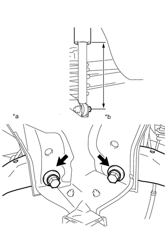
Text in Illustration *a RH Side *b LH Side Suspend the jack on the rear axle spring seat and adjust the length of the rear shock absorber assembly to the reference value.
Length of shock absorber 220 mm (8.66 in.) -
Fully tighten the 2 bolts.
- Torque:
- 90 N*m { 918 kgf*cm, 66 ft.*lbf }
-
-
FULLY TIGHTEN REAR SHOCK ABSORBER ASSEMBLY LH
-
FULLY TIGHTEN REAR SHOCK ABSORBER ASSEMBLY RH
Tech Tips
Use the same procedure for the RH side as for the LH side.
-
ADJUST PARKING BRAKE LEVER TRAVEL
-
BLEED BRAKE LINE
-
BLEED CLUTCH LINE (for Manual Transaxle)
-
for 1KR-FE:
-
for 2NR-FKE, 2ZR-FE:
-
for 1ND-TV:
-
-
INSPECT REAR WHEEL ALIGNMENT
-
CHECK SPEED SENSOR SIGNAL
-
w/ ABS:
-
w/ VSC:
-