REAR AXLE BEAM REMOVAL

PROCEDURE
-
REMOVE REAR WHEEL
-
DRAIN BRAKE FLUID
Note
Immediately wash off any brake fluid that comes into contact with any painted surfaces.
-
SEPARATE SKID CONTROL SENSOR WIRE LH
-
SEPARATE SKID CONTROL SENSOR WIRE RH
Tech Tips
Use the same procedure for the RH side as for the LH side.
-
SEPARATE REAR NO. 4 BRAKE TUBE (for Rear Drum Brake)
-
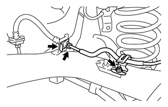
Using a 10 mm union nut wrench, disconnect the rear No. 4 brake tube while holding the rear flexible hose LH with a wrench.
Note
-
Do not kink or damage the brake tube.
-
Do not allow any foreign matter such as dirt and dust to enter the brake line.
-
-
Remove the clip and separate the rear flexible hose LH from the rear axle beam assembly.
-
Remove the nut and separate the rear No. 4 brake tube.
-
-
SEPARATE REAR NO. 3 BRAKE TUBE (for Rear Drum Brake)
Tech Tips
Use the same procedure for the RH side as for the LH side.
-
SEPARATE REAR NO. 4 BRAKE TUBE (for Rear Disc Brake)
-
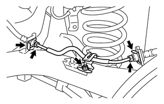
Using a 10 mm union nut wrench, disconnect the rear No. 4 brake tube while holding the rear flexible hose LH with a wrench.
Note
-
Do not kink or damage the brake tube.
-
Do not allow any foreign matter such as dirt and dust to enter the brake line.
-
-
Remove the 2 clips and separate the 2 rear flexible hose LH from the rear axle beam assembly.
-
Remove the nut and separate the rear No. 4 brake tube.
-
-
SEPARATE REAR NO. 3 BRAKE TUBE (for Rear Disc Brake)
Tech Tips
Use the same procedure for the RH side as for the LH side.
-
SEPARATE NO. 3 PARKING BRAKE CABLE ASSEMBLY
-
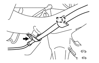
Remove the cable clamp from the rear axle beam assembly.
-
Remove the bolt and separate the No. 3 parking brake cable assembly.
-
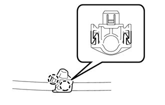
Remove the cable clamp from the No. 3 parking brake cable assembly.
Tech Tips
Replace the clamp with a new one when installing the No. 3 parking brake cable assembly.
-
-
SEPARATE NO. 2 PARKING BRAKE CABLE ASSEMBLY
Tech Tips
Use the same procedure for the RH side as for the LH side.
-
REMOVE REAR BRAKE DRUM SUB-ASSEMBLY (for Rear Drum Brake)
-
SEPARATE REAR DISC BRAKE CALIPER ASSEMBLY LH (for Rear Disc Brake)
-
SEPARATE REAR DISC BRAKE CALIPER ASSEMBLY RH (for Rear Disc Brake)
Tech Tips
Use the same procedure for the RH side as for the LH side.
-
REMOVE REAR DISC (for Rear Disc Brake)
-
REMOVE REAR AXLE HUB AND BEARING ASSEMBLY (for Rear Drum Brake)
-
REMOVE REAR AXLE HUB AND BEARING ASSEMBLY (for Rear Disc Brake)
-
REMOVE FRONT FLOOR CENTER BRACE (for 2ZR-FE)
-
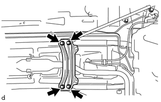
Remove the 4 bolts and front floor center brace from the vehicle.
-
-
REMOVE FRONT FLOOR PANEL BRACE LH (for 2ZR-FE)
-
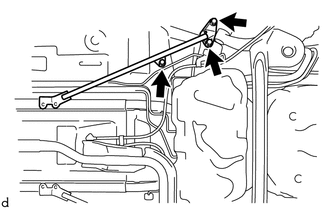
Remove the 3 bolts and front floor panel brace LH from the vehicle.
-
-
REMOVE FRONT FLOOR PANEL BRACE RH (for 2ZR-FE)
Tech Tips
Use the same procedure for the RH side as for the LH side.
-
LOOSEN REAR AXLE BEAM ASSEMBLY
-
REMOVE REAR COIL SPRING
-
Support the spring seat of the rear axle beam assembly using an engine lifter and 2 wooden blocks.
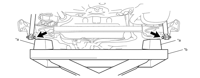
*a Wooden Block *b Engine Lifter -
Remove the 2 bolts and 2 nuts, and separate the rear axle beam assembly from the rear shock absorber assemblies LH and RH.
Note
Because the nut has its own stopper, do not turn the nut. Loosen the bolt with the nut fixed in place.
-
Slowly lower the rear axle beam assembly using engine lifter.
-
Remove the rear coil spring LH, rear coil spring upper insulator LH and rear coil spring lower insulator LH.
-
Remove the rear coil spring RH, rear coil spring upper insulator RH and rear coil spring lower insulator RH.
-
Slowly jack up the rear axle beam assembly using engine lifter, and temporarily tighten the rear axle beam assembly to the rear shock absorber assemblies LH and RH with the 2 bolts and 2 nuts.
Note
Because the nut has its own stopper, do not turn the nut. Loosen the bolt with the nut fixed in place.
-
-
REMOVE REAR AXLE BEAM ASSEMBLY
-
Support the rear axle beam assembly using an engine lifter, 2 wooden blocks and 2 plate lift attachments or equivalent tools.
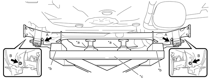
*a Plate Lift Attachment *b Wooden Block *c Engine Lifter - - Note
Make sure to secure the rear axle beam assembly to prevent it from dropping.
-
Remove the 2 bolts A and 2 nuts, and separate the rear axle beam assembly from the rear shock absorber assemblies LH and RH.
Note
Because the nut has its own stopper, do not turn the nut. Loosen the bolt with the nut fixed in place.
-
Remove the 2 bolts B and rear axle beam assembly from the vehicle.
-
-
REMOVE REAR AXLE CARRIER BUSH LH
-
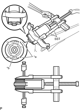
Text in Illustration *a Bend Portions *b Bush Mark Place a matchmark on the rear axle beam assembly with it aligned with the bush mark.
-
Using a chisel and hammer, bend the 2 portions of the bush rib.
Note
Bend the bush rib until the claw of SST can be suspended.
-
Using SST, remove the rear axle carrier bush LH from the rear axle beam assembly.
- SST
- 09950-40011 ( 09951-04020, 09952-04010, 09953-04030, 09954-04020, 09955-04011, 09957-04010, 09958-04011 )
- 09612-30012
- 09950-60010 ( 09951-00590 )
Note
Apply paint to any scratches on the rear axle beam assembly.
-
-
REMOVE REAR AXLE CARRIER BUSH RH
Tech Tips
Use the same procedure for the RH side as for the LH side.