FRONT SUSPENSION MEMBER REMOVAL

PROCEDURE
-
REMOVE CENTER ENGINE UNDER COVER (for 1ND-TV)
-
REMOVE ENGINE UNDER COVER LH (for 1ND-TV)
-
REMOVE ENGINE UNDER COVER RH (for 1ND-TV)
-
PLACE FRONT WHEELS FACING STRAIGHT AHEAD
-
REMOVE FRONT WHEEL
-
REMOVE COLUMN HOLE COVER SILENCER SHEET
-
SEPARATE STEERING SLIDING YOKE SUB-ASSEMBLY
-
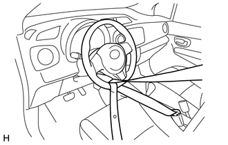
Use a seat belt to fix the steering wheel assembly, in order to avoid breakage of the spiral cable.
-
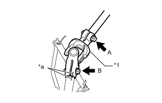
Text in Illustration *1 Steering Sliding Yoke Sub-assembly *a Matchmark Place matchmarks on the steering sliding yoke sub-assembly and steering gear assembly.
-
Loosen bolt A, remove bolt B and separate the steering sliding yoke sub-assembly from the steering gear assembly.
-
-
SEPARATE NO. 1 STEERING COLUMN HOLE COVER SUB-ASSEMBLY
-
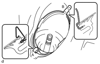
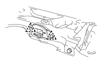
Remove clip A, separate clip B from the body and separate the No. 1 steering column hole cover sub-assembly.
Note
Do not damage clip B.
-
-
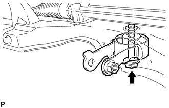
SEPARATE FRONT STABILIZER LINK ASSEMBLY LH
-
Remove the nut and separate the front stabilizer link assembly LH from the front stabilizer bar.
Tech Tips
If the ball joint turns together with the nut, use a 6 mm socket hexagon wrench to hold the stud.
-
-
SEPARATE FRONT STABILIZER LINK ASSEMBLY RH
Tech Tips
Use the same procedure for the RH side as for the LH side.
-
SEPARATE TIE ROD END SUB-ASSEMBLY LH
-
SEPARATE TIE ROD END SUB-ASSEMBLY RH
Tech Tips
Use the same procedure for the RH side as for the LH side.
-
SEPARATE FRONT LOWER SUSPENSION ARM SUB-ASSEMBLY LH
-
SEPARATE FRONT LOWER SUSPENSION ARM SUB-ASSEMBLY RH
Tech Tips
Use the same procedure for the RH side as for the LH side.
-
REMOVE FRONT EXHAUST PIPE ASSEMBLY (for 1KR-FE)
-
REMOVE FRONT EXHAUST PIPE ASSEMBLY (for 2NR-FKE)
-
REMOVE FRONT SUSPENSION MEMBER BRACE SUB-ASSEMBLY (for 2ZR-FE)
-
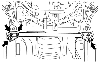
Loosen the 2 nuts.
-
Remove the 2 bolts and front suspension member brace sub-assembly.
-
-
REMOVE FRONT SUSPENSION CROSSMEMBER SUB-ASSEMBLY
-
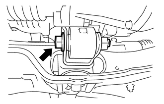
Remove the bolt and separate the engine moving control rod.
-
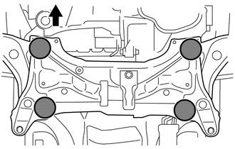
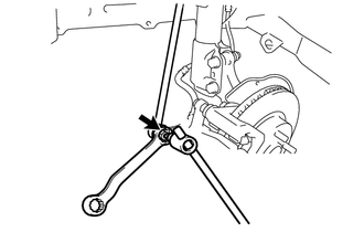
Place wooden blocks or plate lift attachments in the positions shown in the illustration and set an engine lifter underneath the front suspension crossmember sub-assembly.
Text in Illustration 
Front of the Vehicle 
Attachment Placement Positions Note
-
Place the wooden blocks or plate lift attachments so that the front suspension crossmember sub-assembly is level.
-
As the front suspension crossmember sub-assembly is very heavy, be sure to support it securely.
-
-
except 2ZR-FE:
-
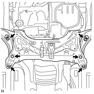
Remove the 6 bolts and front suspension crossmember sub-assembly.
-
-
for 2ZR-FE:
-
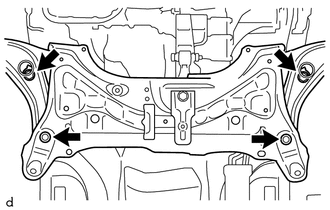
Remove the 4 bolts and front suspension crossmember sub-assembly.
-
-
-
REMOVE MANUAL STEERING GEAR
-
REMOVE FRONT NO. 1 STABILIZER BRACKET LH
-
REMOVE FRONT NO. 1 STABILIZER BRACKET RH
Tech Tips
Use the same procedure for the RH side as for the LH side.
-
REMOVE FRONT STABILIZER BAR
-
REMOVE FRONT LOWER SUSPENSION ARM SUB-ASSEMBLY LH
-
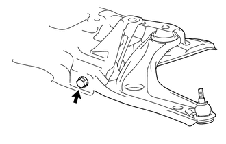
Remove the bolt and front lower suspension arm sub-assembly LH.
-
-
REMOVE FRONT LOWER SUSPENSION ARM SUB-ASSEMBLY RH
Tech Tips
Use the same procedure for the RH side as for the LH side.
-
REMOVE ENGINE MOVING CONTROL ROD COVER (for Cold Area)
-
Remove the 2 clips and engine moving control rod cover.
-
-
REMOVE ENGINE MOVING CONTROL ROD
-
Remove the bolt and engine moving control rod.
-