REAR WHEEL ALIGNMENT INSPECTION
CAUTION / NOTICE / HINT
Note
For vehicles equipped with VSC, if wheel alignment has been adjusted, and if suspension or underbody components have been removed/installed or replaced, be sure to perform the following initialization procedure in order for the system to function normally:
Perform zero point calibration of the yaw rate and acceleration sensor and test mode inspection.
PROCEDURE
-
INSPECT TIRES
-
MEASURE VEHICLE HEIGHT
-
INSPECT CAMBER
-
Install the camber-caster-kingpin gauge and position the rear wheel on the alignment tester.
-
Inspect the camber.
Camber (Unloaded Vehicle) Model Tire Size Engine Camber Except for Rough Road Package 175/70 R14 1KR-FE -0°56' +/- 30' (-0.93° +/- 0.5°) 1NR-FE 175/65 R15 1KR-FE -0°56' +/- 30' (-0.93° +/- 0.5°) 1NR-FE 1ND-TV 195/50 R16 1KR-FE -0°56' +/- 30' (-0.93° +/- 0.5°) 1NR-FE 1ND-TV -0°57' +/- 30' (-0.95° +/- 0.5°) Except for Rough Road Package
S GRADE
195/50 R16 1NR-FE -0°57' +/- 30' (-0.95° +/- 0.5°) 1ND-TV Except for Rough Road Package 175/65 R14 1KR-FE -0°56' +/- 30' (-0.93° +/- 0.5°) 185/60 R15 1KR-FE -0°56' +/- 30' (-0.93° +/- 0.5°) 1NR-FE 1ND-TV Rough Road Package 175/65 R14 1KR-FE -0°53' +/- 30' (-0.88° +/- 0.5°) 185/60 R15 1KR-FE -0°53' +/- 30' (-0.88° +/- 0.5°) 1NR-FE 1ND-TV Note
The tolerance for the difference between the left and right wheels is 30' (0.5°) or less for both cambers. If the camber is not within the specified range, inspect the suspension parts and replace them if necessary.
-
-
INSPECT TOE-IN
Text in Illustration 
Front If the toe-in is not within the specified range, inspect the suspension parts and replace them if necessary.
-
Bounce the vehicle up and down at the corners to stabilize the suspension.
-
Release the parking brake and move the shift lever to N.
-
Push the vehicle straight ahead approximately 5 m (16.4 ft.). (Step A)
-
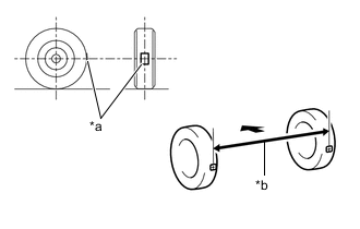
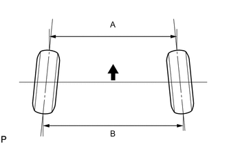
Text in Illustration *a Tread Center Mark *b Dimension B Front of the Vehicle Put tread center marks on the rearmost points of the rear wheels and measure the distance between the marks (Dimension B).
-
Slowly push the vehicle straight ahead to cause the rear wheels to rotate 180°. Use the rear tire valve as a reference point.
Note
Do not allow the wheels to rotate more than 180°. If the wheels rotate more than 180°, perform the procedure from (Step A) again.
-
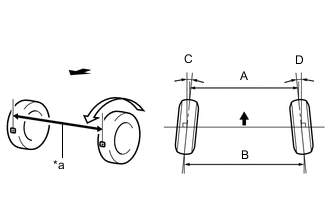
Text in Illustration *a Dimension A Front of the Vehicle Measure the distance between the tread center marks on the front of the rear wheels (Dimension A).
Toe-in (Unloaded Vehicle) Model Tire Size Engine Specified Condition Except for Rough Road Package 175/70 R14 1KR-FE
1NR-FE
C + D: 0°20' +/- 15' ( 0.33° +/- 0.25°) B - A: 3.7 +/- 3.0 mm (0.145 +/- 0.118 in.) 175/65 R15 1KR-FE
1NR-FE
1ND-TV
C + D: 0°20' +/- 15' ( 0.33° +/- 0.25°) B - A: 3.7 +/- 3.0 mm (0.145 +/- 0.118 in.) 195/50 R16 1KR-FE
1NR-FE
1ND-TV
C + D: 0°20' +/- 15' ( 0.33° +/- 0.25°) B - A: 3.7 +/- 3.0 mm (0.145 +/- 0.118 in.) Except for Rough Road Package
S GRADE
195/50 R16 1NR-FE
1ND-TV
C + D: 0°21' +/- 15' ( 0.35° +/- 0.25°) B - A: 3.7 +/- 3.0 mm (0.145 +/- 0.118 in.) Except for Rough Road Package 175/65 R14 1KR-FE C + D: 0°19' +/- 15' ( 0.32° +/- 0.25°) B - A: 3.3 +/- 3.0 mm (0.130 +/- 0.118 in.) 185/60 R15 1KR-FE
1NR-FE
1ND-TV
C + D: 0°19' +/- 15' ( 0.32° +/- 0.25°) B - A: 3.4 +/- 3.0 mm (0.133 +/- 0.118 in.) Rough Road Package 175/65 R14 1KR-FE C + D: 0°15' +/- 15' ( 0.25° +/- 0.25°) B - A: 2.6 +/- 3.0 mm (0.102 +/- 0.118 in.) 185/60 R15 1KR-FE
1NR-FE
1ND-TV
C + D: 0°15' +/- 15' ( 0.25° +/- 0.25°) B - A: 2.6 +/- 3.0 mm (0.102 +/- 0.118 in.)
-
-
PERFORM YAW RATE SENSOR ZERO POINT CALIBRATION