FRONT WHEEL ALIGNMENT ADJUSTMENT
CAUTION / NOTICE / HINT
Note
For vehicles equipped with VSC, if wheel alignment has been adjusted, and if suspension or underbody components have been removed/installed or replaced, be sure to perform the following initialization procedure in order for the system to function normally:
-
Perform zero point calibration of the yaw rate and acceleration sensor and test mode inspection.
-
for TMC Made Click here
-
for TMMF Made Click here
PROCEDURE
-
INSPECT TIRES
-
MEASURE VEHICLE HEIGHT (for TMC Made)
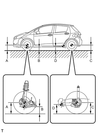
Vehicle Height (Unloaded Vehicle) Model Tire Size Engine Front A-B Rear C-D Except for Rough Road Package 175/70 R14 1KR-FE 95 mm
(3.74 in.)
32 mm
(1.26 in.)
175/65 R15 1KR-FE 95 mm
(3.74 in.)
32 mm
(1.26 in.)
1NR-FE 95 mm
(3.74 in.)
33 mm
(1.30 in.)
175/65 R14 1KR-FE 87 mm
(3.43 in.)
24 mm
(0.94 in.)
185/60 R15 1KR-FE 87 mm
(3.43 in.)
24 mm
(0.94 in.)
1NR-FE 87 mm
(3.43 in.)
24 mm
(0.94 in.)
Rough Road Package 175/65 R14 1KR-FE 67 mm
(2.64 in.)
4 mm
(0.16 in.)
185/60 R15 1KR-FE 67 mm
(2.64 in.)
4 mm
(0.16 in.)
1NR-FE 67 mm
(2.64 in.)
4 mm
(0.16 in.)
Measuring points A Ground clearance of front wheel center B Ground clearance of front lower arm set front bolt center C Ground clearance of rear wheel center D Ground clearance of axle beam set bolt center Note
-
Before inspecting the wheel alignment, check the vehicle height.
-
The standard value shown here is a value that is used for adjusting the wheel alignment and does not indicate the height of an actual vehicle.
Tech Tips
Bounce the vehicle up and down at the corners to stabilize the suspension before inspecting the vehicle height.
-
-
MEASURE VEHICLE HEIGHT (for TMMF Made)
Vehicle Height (Unloaded Vehicle) Model Tire Size Engine Front A-B Rear C-D Except for Rough Road Package 175/70 R14 1KR-FE 95 mm
(3.74 in.)
32 mm
(1.26 in.)
1NR-FE 95 mm
(3.74 in.)
33 mm
(1.30 in.)
1ND-TV 97 mm
(3.82 in.)
33 mm
(1.30 in.)
175/65 R15 1KR-FE 95 mm
(3.74 in.)
32 mm
(1.26 in.)
195/50 R16 1NR-FE 100 mm
(3.94 in.)
33 mm
(1.30 in.)
1ND-TV 100 mm
(3.94 in.)
33 mm
(1.30 in.)
Except for Rough Road Package
w/ Rear Seat
175/65 R14 1KR-FE 87 mm
(3.43 in.)
24 mm
(0.94 in.)
Except for Rough Road Package
w/o Rear Seat
87 mm
(3.43 in.)
21 mm
(0.83 in.)
Except for Rough Road Package
w/ Rear Seat
185/60 R15 1KR-FE 87 mm
(3.43 in.)
24 mm
(0.94 in.)
1NR-FE 87 mm
(3.43 in.)
24 mm
(0.94 in.)
1ND-TV 89 mm
(3.50 in.)
25 mm
(0.98 in.)
Except for Rough Road Package
w/o Rear Seat
1KR-FE 87 mm
(3.43 in.)
21 mm
(0.83 in.)
1NR-FE 87 mm
(3.43 in.)
21 mm
(0.83 in.)
1ND-TV 89 mm
(3.50 in.)
21 mm
(0.83 in.)
Except for Rough Road Package
w/o Panorama Roof
175/65 R15 1NR-FE 95 mm
(3.74 in.)
33 mm
(1.30 in.)
1ND-TV 97 mm
(3.82 in.)
33 mm
(1.30 in.)
Except for Rough Road Package
w/ Panorama Roof
1NR-FE 100 mm
(3.94 in.)
33 mm
(1.30 in.)
1ND-TV 100 mm
(3.94 in.)
33 mm
(1.30 in.)
Rough Road Package 175/65 R14 1KR-FE 67 mm
(2.64 in.)
4 mm
(0.16 in.)
185/60 R15 1KR-FE 67 mm
(2.64 in.)
4 mm
(0.16 in.)
1NR-FE 67 mm
(2.64 in.)
4 mm
(0.16 in.)
1ND-TV 69 mm
(2.72 in.)
5 mm
(0.20 in.)
Measuring points A Ground clearance of front wheel center B Ground clearance of front lower arm set front bolt center C Ground clearance of rear wheel center D Ground clearance of axle beam set bolt center Note
-
Before inspecting the wheel alignment, check the vehicle height.
-
The standard value shown here is a value that is used for adjusting the wheel alignment and does not indicate the height of an actual vehicle.
Tech Tips
Bounce the vehicle up and down at the corners to stabilize the suspension before inspecting the vehicle height.
-
-
INSPECT WHEEL TURNING ANGLE (for TMC Made)
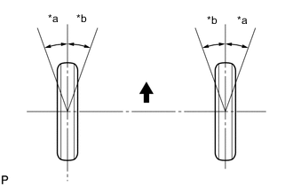
Text in Illustration *a Inside *b Outside 
Front of the Vehicle
-
Fully turn the steering wheel left and right, and measure the wheel turning angle.
Wheel Turning Angle (Unloaded Vehicle) Model Tire Size Engine Inside Wheel Outside Wheel Except for Rough Road Package 175/70 R14 1KR-FE 40°46 ' +/- 2°
(40.77° +/- 2°)
35°05'
(35.08°)
175/65 R15 1KR-FE 40°46 ' +/- 2°
(40.77° +/- 2°)
35°05'
(35.08°)
1NR-FE 40°46' +/- 2°
(40.77° +/- 2°)
35°05'
(35.08°)
175/65 R14 1KR-FE 41°01' +/- 2°
(41.02° +/- 2°)
35°15'
(35.25°)
185/60 R15 1KR-FE 41°01' +/- 2°
(41.02° +/- 2°)
35°15'
(35.25°)
1NR-FE 41°01' +/- 2°
(41.02° +/- 2°)
35°15'
(35.25°)
Rough Road Package 175/65 R14 1KR-FE 41°35' +/- 2°
(41.58° +/- 2°)
35°43'
(35.72°)
185/60 R15 1KR-FE 41°35' +/- 2°
(41.58° +/- 2°)
35°43'
(35.72°)
1NR-FE 41°35' +/- 2°
(41.58° +/- 2°)
35°43'
(35.72°)
If the right and left inside wheel angles are not within the specified range, check the right and left rack end lengths.
-
-
INSPECT WHEEL TURNING ANGLE (for TMMF Made)
Text in Illustration *a Inside *b Outside Front of the Vehicle
-
Fully turn the steering wheel left and right, and measure the wheel turning angle.
Wheel Turning Angle (Unloaded Vehicle) Model Tire Size Engine Inside Wheel Outside Wheel Except for Rough Road Package 175/70 R14 1KR-FE 40°46' +/- 2°
(40.77° +/- 2°)
35°05'
(35.08°)
1NR-FE 40°46' +/- 2°
(40.77° +/- 2°)
35°05'
(35.08° )
1ND-TV 40°45' +/- 2°
(40.75° +/- 2°)
35°03'
(35.05°)
175/65 R15 1KR-FE 40°46' +/- 2°
(40.77° +/- 2°)
35°05'
(35.08°)
195/50 R16 1NR-FE 32°27' +/- 2°
(32.45° +/- 2°)
29°27'
(29.45°)
1ND-TV 32°27' +/- 2°
(32.45° +/- 2°)
29°27'
(29.45°)
Except for Rough Road Package
w/ Rear Seat
175/65 R14 1KR-FE 41°01' +/- 2°
(41.02° +/- 2°)
35°15'
(35.25°)
Except for Rough Road Package
w/o Rear Seat
41°01' +/- 2°
(41.02° +/- 2°)
35°15'
(35.25°)
Except for Rough Road Package
w/ Rear Seat
185/60 R15 1KR-FE 41°01' +/- 2°
(41.02° +/- 2°)
35°15'
(35.25°)
1NR-FE 41°01' +/- 2°
(41.02° +/- 2°)
35°15'
(35.25°)
1ND-TV 40°59' +/- 2°
(40.98° +/- 2°)
35°13'
(35.22°)
Except for Rough Road Package
w/o Rear Seat
1KR-FE 41°01' +/- 2°
(41.02° +/- 2°)
35°15'
(35.25°)
1NR-FE 41°01' +/- 2°
(41.02° +/- 2°)
35°15'
(35.25°)
1ND-TV 40°59' +/- 2°
(40.98° +/- 2°)
35°13'
(35.22°)
Except for Rough Road Package
w/o Panorama Roof
175/65 R15 1NR-FE 40°46' +/- 2°
(40.77° +/- 2°)
35°05'
(35.08°)
1ND-TV 40°45' +/- 2°
(40.75° +/- 2°)
35°03'
(35.05°)
Except for Rough Road Package
w/ Panorama Roof
1NR-FE 40°39' +/- 2°
(40.65° +/- 2°)
34°58'
(34.97°)
1ND-TV 40°39' +/- 2°
(40.65° +/- 2°)
34°58'
(34.97°)
Rough Road Package 175/65 R14 1KR-FE 41°35 +/- 2°
(41.58° +/- 2°)
35°43'
(35.72°)
185/60 R15 1KR-FE 41°35 +/- 2°
(41.58° +/- 2°)
35°43'
(35.72°)
1NR-FE 41°35' +/- 2°
(41.58° +/- 2°)
35°43'
(35.72°)
1ND-TV 41°33' +/- 2°
(41.55° +/- 2°)
35°41'
(35.68°)
If the right and left inside wheel angles are not within the specified range, check the right and left rack end lengths.
-
-
INSPECT CAMBER, CASTER AND STEERING AXIS INCLINATION (for TMC Made)
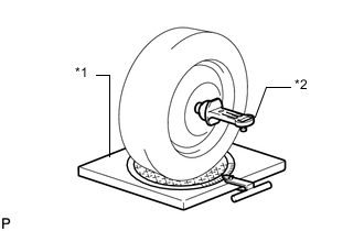
Text in Illustration *1 Alignment tester *2 Camber-caster-steering axis inclination gauge
-
Put the front wheel on the center of the alignment tester.
-
Remove the wheel cap.
-
Set the camber-caster-steering axis inclination gauge at the center of the axle hub or drive shaft.
-
Inspect the camber, caster and steering axis inclination.
Camber Inclination (Unloaded Vehicle) Model Tire Size Engine Camber Except for Rough Road Package 175/70 R14 1KR-FE -0°20' +/- 45'
(-0.33° +/- 0.75°)
175/65 R15 1KR-FE -0°20' +/- 45'
(-0.33° +/- 0.75°)
1NR-FE -0°20' +/- 45'
(-0.33° +/- 0.75°)
175/65 R14 1KR-FE -0°15' +/- 45'
(-0.25° +/- 0.75°)
185/60 R15 1KR-FE -0°15' +/- 45'
(-0.25° +/- 0.75°)
1NR-FE -0°15' +/- 45'
(-0.25° +/- 0.75°)
Rough Road Package 175/65 R14 1KR-FE 0°02' +/- 45'
(0.03° +/- 0.75°)
185/60 R15 1KR-FE 0°02' +/- 45'
(0.03° +/- 0.75°)
1NR-FE 0°02' +/- 45'
(0.03° +/- 0.75°)
Caster Inclination (Unloaded Vehicle) Model Tire Size Engine Caster Except for Rough Road Package 175/70 R14 1KR-FE 5°03' +/- 45'
(5.05° +/- 0.75°)
175/65 R15 1KR-FE 5°03' +/- 45'
(5.05° +/- 0.75°)
1NR-FE 5°01' +/- 45'
(5.02° +/- 0.75°)
175/65 R14 1KR-FE 4°54' +/- 45'
(4.90° +/- 0.75°)
185/60 R15 1KR-FE 4°55' +/- 45'
(4.92° +/- 0.75°)
1NR-FE 4°54' +/- 45'
(4.90° +/- 0.75°)
Rough Road Package 175/65 R14 1KR-FE 4°35' +/- 45'
(4.58° +/- 0.75°)
185/60 R15 1KR-FE 4°35' +/- 45'
(4.58° +/- 0.75°)
1NR-FE 4°35' +/- 45'
(4.58° +/- 0.75°)
Steering Axis Inclination (Unloaded Vehicle) Model Tire Size Engine Steering Axis Inclination
(Reference)
Except for Rough Road Package 175/70 R14 1KR-FE 11°19'
(11.32°)
175/65 R15 1KR-FE 11°19'
(11.32°)
1NR-FE 11°19'
(11.32°)
175/65 R14 1KR-FE 11°09'
(11.15°)
185/60 R15 1KR-FE 11°09'
(11.15°)
1NR-FE 11°09'
(11.15°)
Rough Road Package 175/65 R14 1KR-FE 10°40'
(10.67°)
185/60 R15 1KR-FE 10°40'
(10.67°)
1NR-FE 10°40'
(10.67°)
Note
-
Perform the inspection while the vehicle is empty (without a spare tire or tools on board).
-
The tolerance for the difference between the left and right wheels is 30' (0.5°) or less for both the camber and caster.
-
-
Remove the camber-caster-steering axis inclination gauge and attachment.
-
Install the wheel cap.
If the caster and steering axis inclination are not within the specified values after the camber has been correctly adjusted, recheck the suspension parts for damage and wear.
-
-
INSPECT CAMBER, CASTER AND STEERING AXIS INCLINATION (for TMMF Made)
Text in Illustration *1 Alignment tester *2 Camber-caster-steering axis inclination gauge
-
Put the front wheel on the center of the alignment tester.
-
Remove the wheel cap.
-
Set the camber-caster-steering axis inclination gauge at the center of the axle hub or drive shaft.
-
Inspect the camber, caster and steering axis inclination.
Camber Inclination (Unloaded Vehicle) Model Tire Size Engine Camber Except for Rough Road Package 175/70 R14 1KR-FE -0°20' +/- 45'
(-0.33° +/- 0.75°)
1NR-FE -0°20' +/- 45'
(-0.33° +/- 0.75°)
1ND-TV -0°21' +/- 45'
(-0.35° +/- 0.75°)
175/65 R15 1KR-FE -0°20' +/- 45'
(-0.33° +/- 0.75°)
195/50 R16 1NR-FE -0°23' +/- 45'
(-0.38° +/- 0.75°)
1ND-TV -0°23' +/- 45'
(-0.38° +/- 0.75°)
Except for Rough Road Package
w/ Rear Seat
175/65 R14 1KR-FE -0°15' +/- 45'
(-0.25° +/- 0.75°)
Except for Rough Road Package
w/o Rear Seat
-0°15' +/- 45'
(-0.25° +/- 0.75°)
Except for Rough Road Package
w/ Rear Seat
185/60 R15 1KR-FE -0°15' +/- 45'
(-0.25° +/- 0.75°)
1NR-FE -0°15' +/- 45'
(-0.25° +/- 0.75°)
1ND-TV -0°16' +/- 45'
(-0.27° +/- 0.75°)
Except for Rough Road Package
w/o Rear Seat
1KR-FE -0°15' +/- 45'
(-0.25° +/- 0.75°)
1NR-FE -0°15' +/- 45'
(-0.25° +/- 0.75°)
1ND-TV -0°16' +/- 45'
(-0.27° +/- 0.75°)
Except for Rough Road Package
w/o Panorama Roof
175/65 R15 1NR-FE -0°20' +/- 45'
(-0.33° +/- 0.75°)
1ND-TV -0°21' +/- 45'
(-0.35° +/- 0.75°)
Except for Rough Road Package
w/ Panorama Roof
1NR-FE -0°23' +/- 45'
(-0.38° +/- 0.75°)
1ND-TV -0°23' +/- 45'
(-0.38° +/- 0.75°)
Rough Road Package 175/65 R14 1KR-FE 0°02' +/- 45'
(0.03° +/- 0.75°)
185/60 R15 1KR-FE 0°02' +/- 45'
(0.03° +/- 0.75°)
1NR-FE 0°02' +/- 45'
(0.03° +/- 0.75°)
1ND-TV 0°01' +/- 45'
(0.02° +/- 0.75°)
Caster Inclination (Unloaded Vehicle) Model Tire Size Engine Caster Except for Rough Road Package 175/70 R14 1KR-FE 5°03' +/- 45'
(5.05° +/- 0.75°)
1NR-FE 5°01' +/- 45'
(5.02° +/- 0.75°)
1ND-TV 5°00' +/- 45'
(5.00° +/- 0.75°)
175/65 R15 1KR-FE 5°03' +/- 45'
(5.05° +/- 0.75°)
195/50 R16 1NR-FE 5°00' +/- 45'
(5.00° +/- 0.75°)
1ND-TV 4°59' +/- 45'
(4.98° +/- 0.75°)
Except for Rough Road Package
w/ Rear Seat
175/65 R14 1KR-FE 4°54' +/- 45'
(4.90° +/- 0.75°)
Except for Rough Road Package
w/o Rear Seat
4°48' +/- 45'
(4.80° +/- 0.75°)
Except for Rough Road Package
w/ Rear Seat
185/60 R15 1KR-FE 4°55' +/- 45'
(4.92° +/- 0.75°)
1NR-FE 4°54' +/- 45'
(4.90° +/- 0.75°)
1ND-TV 4°52' +/- 45'
(4.87° +/- 0.75°)
Except for Rough Road Package
w/o Rear Seat
1KR-FE 4°49' +/- 45'
(4.82° +/- 0.75°)
1NR-FE 4°48' +/- 45'
(4.80° +/- 0.75°)
1ND-TV 4°46' +/- 45'
(4.77° +/- 0.75°)
Except for Rough Road Package
w/o Panorama Roof
175/65 R15 1NR-FE 5°01' +/- 45'
(5.02° +/- 0.75°)
1ND-TV 5°00' +/- 45'
(5.00° +/- 0.75°)
Except for Rough Road Package
w/ Panorama Roof
1NR-FE 5°00' +/- 45'
(5.00° +/- 0.75°)
1ND-TV 4°59' +/- 45'
(4.98° +/- 0.75°)
Rough Road Package 175/65 R14 1KR-FE 4°35' +/- 45'
(4.58° +/- 0.75°)
185/60 R15 1KR-FE 4°35' +/- 45'
(4.58° +/- 0.75°)
1NR-FE 4°35' +/- 45'
(4.58° +/- 0.75°)
1ND-TV 4°32' +/- 45'
(4.53° +/- 0.75°)
Steering Axis Inclination (Unloaded Vehicle) Model Tire Size Engine Steering Axis Inclination
(Reference)
Except for Rough Road Package 175/70 R14 1KR-FE 11°19'
(11.32°)
1NR-FE 11°19'
(11.32°)
1ND-TV 11°21'
(11.35°)
175/65 R15 1KR-FE 11°19'
(11.32°)
195/50 R16 1NR-FE 11°25'
(11.42°)
1ND-TV 11°25'
(11.42°)
Except for Rough Road Package
w/ Rear Seat
175/65 R14 1KR-FE 11°09'
(11.15°)
Except for Rough Road Package
w/o Rear Seat
11°09'
(11.15°)
Except for Rough Road Package
w/ Rear Seat
185/60 R15 1KR-FE 11°09'
(11.15°)
1NR-FE 11°09'
(11.15°)
1ND-TV 11°11'
(11.18°)
Except for Rough Road Package
w/o Rear Seat
1KR-FE 11°09'
(11.15°)
1NR-FE 11°09'
(11.15°)
1ND-TV 11°11'
(11.18°)
Except for Rough Road Package
w/o Panorama Roof
175/65 R15 1NR-FE 11°19'
(11.32°)
1ND-TV 11°21'
(11.35°)
Except for Rough Road Package
w/ Panorama Roof
1NR-FE 11°25'
(11.42°)
1ND-TV 11°25'
(11.42°)
Rough Road Package 175/65 R14 1KR-FE 10°40'
(10.67°)
185/60 R15 1KR-FE 10°40'
(10.67°)
1NR-FE 10°40'
(10.67°)
1ND-TV 10°42'
(10.70°)
Note
-
Perform the inspection while the vehicle is empty (without a spare tire or tools on board).
-
The tolerance for the difference between the left and right wheels is 30' (0.5°) or less for both the camber and caster.
-
-
Remove the camber-caster-steering axis inclination gauge and attachment.
-
Install the wheel cap.
If the caster and steering axis inclination are not within the specified values after the camber has been correctly adjusted, recheck the suspension parts for damage and wear.
-
-
ADJUST CAMBER
Note
Inspect the toe-in after the camber has been adjusted.
-
Remove the front wheel.
-
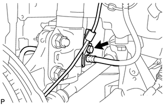
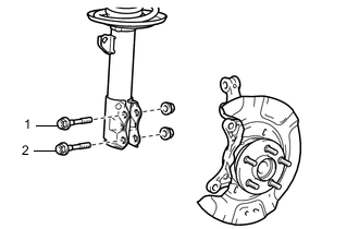
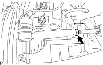
Remove the bolt and separate the speed sensor and flexible hose.
-
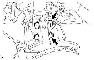
Remove the 2 nuts from the lower side of the shock absorber.
Tech Tips
Keep the bolt from rotating while loosening and removing the nuts.
-
Clean the installation surfaces of the shock absorber and steering knuckle.
-
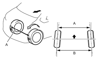
Provisionally install the 2 nuts (Step A).
-
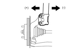
Fully push or pull the axle hub in the direction of the required adjustment (Step B).
-
Tighten the 2 nuts.
- Torque:
- 164 N*m { 1672 kgf*cm, 121 ft.*lbf }
Tech Tips
Keep the bolt from rotating while loosening and removing the nuts.
-
Install the flexible hose and speed sensor with the bolt.
- Torque:
- 29 N*m { 300 kgf*cm, 22 ft.*lbf }
Note
Install the flexible hose and speed sensor without twisting them.
-
Install the front wheel.
- Torque:
- 103 N*m { 1050 kgf*cm, 76 ft.*lbf }
-
Check the camber.
If the measured value is not within the specifications, calculate the required adjustment amount using the formula below.
(Camber adjustment amount) = Center of specified range - Measured value
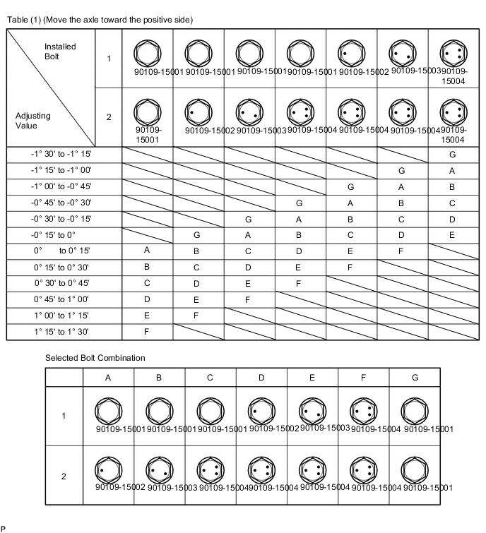
Check the combination of installed bolts. Select appropriate bolts from the table below to adjust the camber to within the specified range.
Tech Tips
Try to adjust the camber to the center of the specified range.
Move axle toward (+) in step (B) Refer to table (1) (Move axle toward positive side) Move axle toward (-) in step (B) Refer to table (2) (Move axle toward negative side) -
Table (1) (Move the axle toward the positive side)
-
Table (2) (Move the axle toward the negative side).
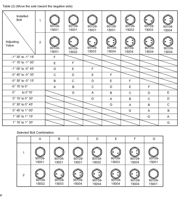
The body and suspension may be damaged if the camber is not correctly adjusted in accordance with the above table.
Note
Replace the nut with a new one when replacing the bolt.
-
Repeat the steps mentioned above. At step (A), replace 1 or 2 selected bolts.
Tech Tips
Replace one bolt at a time when replacing 2 bolts.
-
-
INSPECT TOE-IN (for TMC Made)
-
Bounce the vehicle up and down at the corners to stabilize the suspension.
-
Release the parking brake and move the shift lever to the neutral position.
-
Push the vehicle straight ahead approximately 5 m (16.4 ft.). (Step A)
-
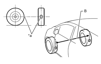
Text in Illustration *a Tread Center Mark Put tread center marks on the rearmost points of the front wheels and measure the distance between the marks (Dimension B).
-
Slowly push the vehicle straight ahead to cause the front wheels to rotate 180° using the front tire valve as a reference point.
Tech Tips
Do not allow the wheels to rotate more than 180°. If the wheels rotate more than 180°, perform the procedure from (Step A) again.
-
Measure the distance between the tread center marks on the front side of the wheels (Dimension A).
Text in Illustration Front of the Vehicle Toe-in (Unloaded Vehicle) Model Tire Size Engine Specified Condition Except for Rough Road Package 175/70 R14 1KR-FE B-A: 1.3 +/- 2.0 mm
(0.0512 +/- 0.0787 in.)
175/65 R15 1KR-FE B-A: 1.3 +/- 2.0 mm
(0.0512 +/- 0.0787 in.)
1NR-FE B-A: 1.3 +/- 2.0 mm
(0.0512 +/- 0.0787 in.)
175/65 R14 1KR-FE B-A: 1.3 +/- 2.0 mm
(0.0512 +/- 0.0787 in.)
185/60 R15 1KR-FE B-A: 1.3 +/- 2.0 mm
(0.0512 +/- 0.0787 in.)
1NR-FE B-A: 1.3 +/- 2.0 mm
(0.0512 +/- 0.0787 in.)
Rough Road Package 175/65 R14 1KR-FE B-A: 1.3 +/- 2.0 mm
(0.0512 +/- 0.0787 in.)
185/60 R15 1KR-FE B-A: 1.4 +/- 2.0 mm
(0.0551 +/- 0.0787 in.)
1NR-FE B-A: 1.4 +/- 2.0 mm
(0.0551 +/- 0.0787 in.)
If the toe-in is not within the specified value, adjust it at the rack ends.
-
-
INSPECT TOE-IN (for TMMF Made)
-
Bounce the vehicle up and down at the corners to stabilize the suspension.
-
Release the parking brake and move the shift lever to the neutral position.
-
Push the vehicle straight ahead approximately 5 m (16.4 ft.). (Step A)
-
Text in Illustration *a Tread Center Mark Put tread center marks on the rearmost points of the front wheels and measure the distance between the marks (Dimension B).
-
Slowly push the vehicle straight ahead to cause the front wheels to rotate 180° using the front tire valve as a reference point.
Tech Tips
Do not allow the wheels to rotate more than 180°. If the wheels rotate more than 180°, perform the procedure from (Step A) again.
-
Measure the distance between the tread center marks on the front side of the wheels (Dimension A).
Text in Illustration Front of the Vehicle Toe-in (Unloaded Vehicle) Model Tire Size Engine Specified Condition Except for Rough Road Package 175/70 R14 1KR-FE B-A: 1.3 +/- 2.0 mm
(0.0512 +/- 0.0787 in.)
1NR-FE B-A: 1.3 +/- 2.0 mm
(0.0512 +/- 0.0787 in.)
1ND-TV B-A: 1.2 +/- 2.0 mm
(0.0472 +/- 0.0787 in.)
175/65 R15 1KR-FE B-A: 1.3 +/- 2.0 mm
(0.0512 +/- 0.0787 in.)
195/50 R16 1NR-FE B-A: 1.0 +/- 2.0 mm
(0.0393 +/- 0.0787 in.)
1ND-TV B-A: 1.0 +/- 2.0 mm
(0.0393 +/- 0.0787 in.)
Except for Rough Road Package
w/ Rear Seat
175/65 R14 1KR-FE B-A: 1.3 +/- 2.0 mm
(0.0512 +/- 0.0787 in.)
Except for Rough Road Package
w/o Rear Seat
B-A: 1.3 +/- 2.0 mm
(0.0512 +/- 0.0787 in.)
Except for Rough Road Package
w/ Rear Seat
185/60 R15 1KR-FE B-A: 1.3 +/- 2.0 mm
(0.0512 +/- 0.0787 in.)
1NR-FE B-A: 1.3 +/- 2.0 mm
(0.0512 +/- 0.0787 in.)
1ND-TV B-A: 1.2 +/- 2.0 mm
(0.0472 +/- 0.0787 in.)
Except for Rough Road Package
w/o Rear Seat
1KR-FE B-A: 1.3 +/- 2.0 mm
(0.0512 +/- 0.0787 in.)
1NR-FE B-A: 1.3 +/- 2.0 mm
(0.0512 +/- 0.0787 in.)
1ND-TV B-A: 1.2 +/- 2.0 mm
(0.0472 +/- 0.0787 in.)
Except for Rough Road Package
w/o Panorama Roof
175/65 R15 1NR-FE B-A: 1.3 +/- 2.0 mm
(0.0512 +/- 0.0787 in.)
1ND-TV B-A: 1.2 +/- 2.0 mm
(0.0472 +/- 0.0787 in.)
Except for Rough Road Package
w/ Panorama Roof
1NR-FE B-A: 1.0 +/- 2.0 mm
(0.0393 +/- 0.0787 in.)
1ND-TV B-A: 1.0 +/- 2.0 mm
(0.0393 +/- 0.0787 in.)
Rough Road Package 175/65 R14 1KR-FE B-A: 1.3 +/- 2.0 mm
(0.0512 +/- 0.0787 in.)
185/60 R15 1KR-FE B-A: 1.4 +/- 2.0 mm
(0.0551 +/- 0.0787 in.)
1NR-FE B-A: 1.4 +/- 2.0 mm
(0.0551 +/- 0.0787 in.)
1ND-TV B-A: 1.3 +/- 2.0 mm
(0.0512 +/- 0.0787 in.)
If the toe-in is not within the specified value, adjust it at the rack ends.
-
-
ADJUST TOE-IN (for TMC Made)
-
Measure the thread lengths of the right and left rack ends.
Standard Difference in thread length of 1.5 mm (0.0591 in.) or less -
Remove the rack boot set clips.
-
Loosen the tie rod end lock nuts.
-
Adjust the rack ends if the difference in thread length between the right and left rack ends is not within the specified range.
-
Extend the shorter rack end if the measured toe-in deviates toward the outer-side.
-
Shorten the longer rack end if the measured toe-in deviates toward the inner-side.
-
-
Turn the right and left rack ends by an equal amount to adjust the toe-in.
Tech Tips
Try to adjust the toe-in to the center of the specified range.
-
Make sure that the lengths of the right and left rack ends are the same.
Toe-in (Unloaded Vehicle) Model Tire Size Engine Specified Condition Except for Rough Road Package 175/70 R14 1KR-FE B-A: 1.3 +/- 2.0 mm
(0.0512 +/- 0.0787 in.)
175/65 R15 1KR-FE B-A: 1.3 +/- 2.0 mm
(0.0512 +/- 0.0787 in.)
1NR-FE B-A: 1.3 +/- 2.0 mm
(0.0512 +/- 0.0787 in.)
175/65 R14 1KR-FE B-A: 1.3 +/- 2.0 mm
(0.0512 +/- 0.0787 in.)
185/60 R15 1KR-FE B-A: 1.3 +/- 2.0 mm
(0.0512 +/- 0.0787 in.)
1NR-FE B-A: 1.3 +/- 2.0 mm
(0.0512 +/- 0.0787 in.)
Rough Road Package 175/65 R14 1KR-FE B-A: 1.3 +/- 2.0 mm
(0.0512 +/- 0.0787 in.)
185/60 R15 1KR-FE B-A: 1.4 +/- 2.0 mm
(0.0551 +/- 0.0787 in.)
1NR-FE B-A: 1.4 +/- 2.0 mm
(0.0551 +/- 0.0787 in.)
-
Tighten the tie rod end lock nuts to the specified torque.
- Torque:
- 75 N*m { 760 kgf*cm, 55 ft.*lbf }
Note
Provisionally tighten the lock nut while holding the hexagonal part of the steering rack end so that the lock nut and the steering rack end do not turn together. Hold the flat of the tie rod end and tighten the lock nut.
-
Place the boots on the seats.
-
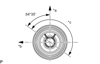
Text in Illustration *a Upper Side *b Front Side *c 180° (Clip installation range) Using pliers, install the RH and LH boot clips as shown in the illustration.
Note
-
Install the clip so that its claws are within the clip installation range.
-
Make sure that the rack boots are not twisted.
-
-
-
ADJUST TOE-IN (for TMMF Made)
-
Measure the thread lengths of the right and left rack ends.
Standard Difference in thread length of 1.5 mm (0.0591 in.) or less -
Remove the rack boot set clips.
-
Loosen the tie rod end lock nuts.
-
Adjust the rack ends if the difference in thread length between the right and left rack ends is not within the specified range.
-
Extend the shorter rack end if the measured toe-in deviates toward the outer-side.
-
Shorten the longer rack end if the measured toe-in deviates toward the inner-side.
-
-
Turn the right and left rack ends by an equal amount to adjust the toe-in.
Tech Tips
Try to adjust the toe-in to the center of the specified range.
-
Make sure that the lengths of the right and left rack ends are the same.
Toe-in (Unloaded Vehicle) Model Tire Size Engine Specified Condition Except for Rough Road Package 175/70 R14 1KR-FE B-A: 1.3 +/- 2.0 mm
(0.0512 +/- 0.0787 in.)
1NR-FE B-A: 1.3 +/- 2.0 mm
(0.0512 +/- 0.0787 in.)
1ND-TV B-A: 1.2 +/- 2.0 mm
(0.0472 +/- 0.0787 in.)
175/65 R15 1KR-FE B-A: 1.3 +/- 2.0 mm
(0.0512 +/- 0.0787 in.)
195/50 R16 1NR-FE B-A: 1.0 +/- 2.0 mm
(0.0393 +/- 0.0787 in.)
1ND-TV B-A: 1.0 +/- 2.0 mm
(0.0393 +/- 0.0787 in.)
Except for Rough Road Package
w/ Rear Seat
175/65 R14 1KR-FE B-A: 1.3 +/- 2.0 mm
(0.0512 +/- 0.0787 in.)
Except for Rough Road Package
w/o Rear Seat
B-A: 1.3 +/- 2.0 mm
(0.0512 +/- 0.0787 in.)
Except for Rough Road Package
w/ Rear Seat
185/60 R15 1KR-FE B-A: 1.3 +/- 2.0 mm
(0.0512 +/- 0.0787 in.)
1NR-FE B-A: 1.3 +/- 2.0 mm
(0.0512 +/- 0.0787 in.)
1ND-TV B-A: 1.2 +/- 2.0 mm
(0.0472 +/- 0.0787 in.)
Except for Rough Road Package
w/o Rear Seat
1KR-FE B-A: 1.3 +/- 2.0 mm
(0.0512 +/- 0.0787 in.)
1NR-FE B-A: 1.3 +/- 2.0 mm
(0.0512 +/- 0.0787 in.)
1ND-TV B-A: 1.2 +/- 2.0 mm
(0.0472 +/- 0.0787 in.)
Except for Rough Road Package
w/o Panorama Roof
175/65 R15 1NR-FE B-A: 1.3 +/- 2.0 mm
(0.0512 +/- 0.0787 in.)
1ND-TV B-A: 1.2 +/- 2.0 mm
(0.0472 +/- 0.0787 in.)
Except for Rough Road Package
w/ Panorama Roof
1NR-FE B-A: 1.0 +/- 2.0 mm
(0.0393 +/- 0.0787 in.)
1ND-TV B-A: 1.0 +/- 2.0 mm
(0.0393 +/- 0.0787 in.)
Rough Road Package 175/65 R14 1KR-FE B-A: 1.3 +/- 2.0 mm
(0.0512 +/- 0.0787 in.)
185/60 R15 1KR-FE B-A: 1.4 +/- 2.0 mm
(0.0551 +/- 0.0787 in.)
1NR-FE B-A: 1.4 +/- 2.0 mm
(0.0551 +/- 0.0787 in.)
1ND-TV B-A: 1.3 +/- 2.0 mm
(0.0512 +/- 0.0787 in.)
-
Tighten the tie rod end lock nuts to the specified torque.
- Torque:
- 75 N*m { 760 kgf*cm, 55 ft.*lbf }
Note
Provisionally tighten the lock nut while holding the hexagonal part of the steering rack end so that the lock nut and the steering rack end do not turn together. Hold the flat of the tie rod end and tighten the lock nut.
-
Place the boots on the seats.
-
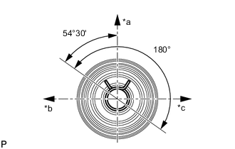
Text in Illustration *a Upper Side *b Front Side *c Rear Side Using pliers, install the clip as shown in the illustration.
Note
Make sure that the boots are not twisted.
-
-
FRONT WHEELS FACING STRAIGHT AHEAD
-
PERFORM YAW RATE SENSOR ZERO POINT CALIBRATION (for TMC Made)
-
PERFORM YAW RATE SENSOR ZERO POINT CALIBRATION (for TMMF Made)