FRONT SUSPENSION MEMBER INSTALLATION

PROCEDURE
-
INSTALL ENGINE MOVING CONTROL ROD
-
Install the engine moving control rod with the bolt.
- Torque:
- 110 N*m { 1122 kgf*cm, 81 ft.*lbf }
Tech Tips
Temporarily tighten the transaxle side, and then tighten the bolt to the specified torque.
-
-
INSTALL ENGINE MOVING CONTROL ROD COVER (for Cold Area)
-
Install the engine moving control rod cover with the 2 clips.
-
-
TEMPORARILY TIGHTEN FRONT LOWER SUSPENSION ARM SUB-ASSEMBLY LH
-
Install the front lower suspension arm sub-assembly LH with the bolt.
-
-
TEMPORARILY TIGHTEN FRONT LOWER SUSPENSION ARM SUB-ASSEMBLY RH
Tech Tips
Use the same procedure for the RH side as for the LH side.
-
INSTALL FRONT STABILIZER BAR
-
INSTALL FRONT NO. 1 STABILIZER BRACKET LH
-
INSTALL FRONT NO. 1 STABILIZER BRACKET RH
Tech Tips
Use the same procedure for the RH side as for the LH side.
-
INSTALL MANUAL STEERING GEAR
-
INSTALL FRONT SUSPENSION CROSSMEMBER SUB-ASSEMBLY
-
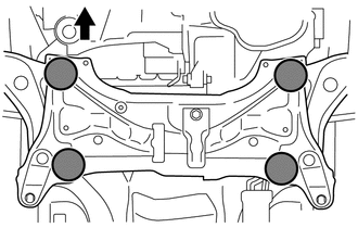
Place wooden blocks or plate lift attachments on an engine lifter, and then set the front suspension crossmember sub-assembly so that the attachments are in the positions shown in the illustration.
Text in Illustration 
Front of the Vehicle 
Attachment Placement Positions -
Provisionally install the front suspension crossmember sub-assembly onto the body with the 6 bolts.
-
By inserting SST into the datum holes in the front suspension crossmembers RH and LH alternately, tighten bolts A, B and C on both sides to the specified torque, in several steps.
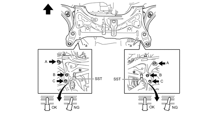
Text in Illustration *a Datum Hole - - Front of the Vehicle - - - SST
- 09670-00011
- 09670-00020
- Torque:
- Bolt A
- 87 N*m { 887 kgf*cm, 64 ft.*lbf }
- Bolt B
- 151 N*m { 1540 kgf*cm, 111 ft.*lbf }
- Bolt C
- 98 N*m { 999 kgf*cm, 72 ft.*lbf }
Note
-
Insert SST into the datum hole in a vertical orientation.
-
If SST cannot be inserted into the datum hole vertically, loosen all the bolts and then insert SST again.
-
Install the engine moving control rod with the bolt.
- Torque:
- 120 N*m { 1224 kgf*cm, 89 ft.*lbf }
-
-
INSTALL FRONT LOWER SUSPENSION ARM SUB-ASSEMBLY LH
-
INSTALL FRONT LOWER SUSPENSION ARM SUB-ASSEMBLY RH
Tech Tips
Use the same procedure for the RH side as for the LH side.
-
INSTALL FRONT EXHAUST PIPE ASSEMBLY (for 1KR-FE)
-
INSTALL FRONT EXHAUST PIPE ASSEMBLY (for 1NR-FE)
-
INSTALL TIE ROD END SUB-ASSEMBLY LH
-
INSTALL TIE ROD END SUB-ASSEMBLY RH
Tech Tips
Use the same procedure for the RH side as for the LH side.
-
INSTALL FRONT STABILIZER LINK ASSEMBLY LH
-
Install the front stabilizer link assembly LH with the nut.
- Torque:
- 74 N*m { 755 kgf*cm, 55 ft.*lbf }
Tech Tips
If the ball joint turns together with the nut, use a socket hexagon wrench 6 to hold the stud.
-
-
INSTALL FRONT STABILIZER LINK ASSEMBLY RH
Tech Tips
Use the same procedure for the RH side as for the LH side.
-
INSTALL NO. 1 STEERING COLUMN HOLE COVER SUB-ASSEMBLY
-
Install clip B onto the body portion and install the No. 1 steering column hole cover onto the body portion with clip A.
Note
Make sure that the lip portion of steering column hole cover is not damaged.
-
-
INSTALL STEERING SLIDING YOKE SUB-ASSEMBLY
-
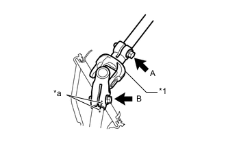
Text in Illustration *1 Steering Sliding Yoke Sub-assembly *a Matchmarks Align the matchmarks and install the steering sliding yoke sub-assembly onto the power steering gear.
-
Install the bolt B.
- Torque:
- 35 N*m { 360 kgf*cm, 26 ft.*lbf }
-
Tighten bolt A.
- Torque:
- 35 N*m { 360 kgf*cm, 26 ft.*lbf }
-
-
INSTALL COLUMN HOLE COVER SILENCER SHEET
-
INSTALL FRONT WHEEL
- Torque:
- 103 N*m { 1050 kgf*cm, 76 ft.*lbf }
-
POSITION WHEELS FACING STRAIGHT AHEAD
-
STABILIZE SUSPENSION
-
Lower the vehicle.
-
Bounce the vehicle up and down several times to stabilize the suspension.
-
-
FULLY TIGHTEN FRONT LOWER SUSPENSION ARM SUB-ASSEMBLY LH
-
FULLY TIGHTEN FRONT LOWER SUSPENSION ARM SUB-ASSEMBLY RH
Tech Tips
Use the same procedure for the RH side as for the LH side.
-
INSPECT FOR EXHAUST GAS LEAK (for 1KR-FE)
-
INSPECT FOR EXHAUST GAS LEAK (for 1NR-FE)
Tech Tips
Perform "Inspection After Repairs" after repairing or replacing the exhaust system Click here.
-
INSTALL ENGINE UNDER COVER RH (for 1ND-TV)
-
INSTALL ENGINE UNDER COVER LH (for 1ND-TV)
-
INSTALL CENTER ENGINE UNDER COVER (for 1ND-TV)
-
INSPECT AND ADJUST FRONT WHEEL ALIGNMENT
-
CHECK SPEED SENSOR SIGNAL (w/o VSC)
-
CHECK SPEED SENSOR SIGNAL (for TMC Made with VSC)
-
CHECK SPEED SENSOR SIGNAL (for TMMF Made with VSC)