FRONT DRIVE SHAFT ASSEMBLY(for 2NR-FKE) INSTALLATION

PROCEDURE
-
INSTALL FRONT DRIVE SHAFT ASSEMBLY LH
Tech Tips
Install so that the gap between the front drive inboard joint assembly and the transaxle is the same as the gap measured at the time of removal.
-
for CVT:
-
Coat the splines of the front drive inboard joint assembly with Toyota genuine CVT fluid FE.
-
-
for Manual Transaxle:
-
Coat the spline of the front drive inboard joint assembly with gear oil.
-
-
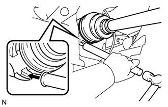
Align the front drive inboard joint assembly splines and install the front drive shaft assembly LH with a brass bar and hammer.
Note
-
Face the cut area of the front drive shaft hole snap ring downward.
-
Do not damage the oil seal.
-
Do not damage the front axle inboard joint boot.
-
-
-
INSTALL FRONT DRIVE SHAFT ASSEMBLY RH
Tech Tips
Use the same procedure for the RH side as for the LH side.
-
INSTALL FRONT AXLE ASSEMBLY LH
-
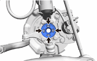

Toyota Body Grease W Apply TOYOTA body grease W to the entire contact surface between the front drive shaft assembly and front axle hub sub-assembly surface or only apply 0.1 to 0.3 g (0.00353 to 0.0105 oz.) of TOYOTA body grease W to the 4 areas on the axle hub bearing shown in the illustration.
-
Push the front axle assembly LH out of the vehicle to align the spline of the front drive shaft assembly LH with the front axle assembly and insert the front axle assembly LH.
Note
-
Do not push the front axle assembly LH further out of the vehicle than is necessary.
-
Do not damage the front axle outboard joint boot.
-
Check for any foreign matter on the speed sensor rotor and insertion part.
-
Do not damage the speed sensor rotor.
-
-
-
INSTALL FRONT AXLE ASSEMBLY RH
Tech Tips
Use the same procedure for the RH side as for the LH side.
-
INSTALL DRIVE SHAFT HEAT INSULATOR SUB-ASSEMBLY
-
Install the drive shaft heat insulator sub-assembly with the 2 bolts.
- Torque:
- 23.5 N*m { 240 kgf*cm, 17 ft.*lbf }
-
-
INSTALL FRONT LOWER SUSPENSION ARM SUB-ASSEMBLY LH
-
INSTALL FRONT LOWER SUSPENSION ARM SUB-ASSEMBLY RH
Tech Tips
Use the same procedure for the RH side as for the LH side.
-
INSTALL TIE ROD END SUB-ASSEMBLY LH
-
INSTALL TIE ROD END SUB-ASSEMBLY RH
Tech Tips
Use the same procedure for the RH side as for the LH side.
-
INSTALL FRONT STABILIZER LINK ASSEMBLY LH
-
INSTALL FRONT STABILIZER LINK ASSEMBLY RH
Tech Tips
Use the same procedure for the RH side as for the LH side.
-
INSTALL FRONT SPEED SENSOR LH
-
Install the front speed sensor onto the steering knuckle LH with the bolt.
- Torque:
- 8.5 N*m { 87 kgf*cm, 75 in.*lbf }
Note
-
Check that the speed sensor tip and installation portion are free of foreign matter.
-
Install the speed sensor without turning it from its original installation angle.
-
Install the front flexible hose and front speed sensor LH with the bolt.
- Torque:
- 29 N*m { 300 kgf*cm, 22 ft.*lbf }
Note
Install the front flexible hose and front speed sensor LH without twisting them.
-
-
INSTALL FRONT SPEED SENSOR RH
Tech Tips
Use the same procedure for the RH side as for the LH side.
-
INSTALL FRONT AXLE SHAFT NUT LH
-
Clean the threaded parts on the front drive shaft assembly LH and front axle shaft nut LH using a non-residue solvent.
Note
-
Be sure to perform this work for a new front drive shaft assembly LH.
-
Keep the threaded parts free of oil and foreign objects.
-
-
Using a deep socket wrench 30 mm, install a new front axle shaft nut LH.
- Torque:
- 216 N*m { 2203 kgf*cm, 159 ft.*lbf }
-
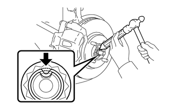
Using a chisel and hammer, stake the axle shaft nut LH.
-
-
INSTALL FRONT AXLE SHAFT NUT RH
Tech Tips
Use the same procedure for the RH side as for the LH side.
-
INSPECT AND ADJUST CONTINUOUSLY VARIABLE TRANSAXLE FLUID (for CVT)
-
INSPECT FOR OIL LEAK
-
INSTALL ENGINE UNDER COVER RH
-
INSTALL ENGINE UNDER COVER LH
-
INSTALL FRONT WHEEL
- Torque:
- 103 N*m { 1050 kgf*cm, 76 ft.*lbf }
-
INSPECT AND ADJUST FRONT WHEEL ALIGNMENT