FRONT AXLE HUB(for TMMF Made) INSTALLATION

CAUTION / NOTICE / HINT
Tech Tips
-
Use the same procedure for the RH side as for the LH side.
-
The procedure listed below is for the LH side.
PROCEDURE
-
INSTALL FRONT AXLE HUB BEARING
-
INSTALL FRONT AXLE HUB SUB-ASSEMBLY
-
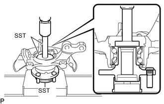
Using SST and a press, press the axle hub into the steering knuckle.
- SST
- 09950-70010 ( 09951-07100 )
- 09950-60010 ( 09951-00580 )
- 09608-32010
-
-
INSTALL FRONT AXLE HUB HOLE SNAP RING
-
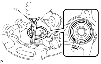
Text in Illustration *1 Snap Ring Pliers *a Speed Sensor Installation Gap Using snap ring pliers, install a new axle hub hole snap ring, as shown in the illustration.
Note
-
Do not overlap the end of the snap ring and the installation hole in the speed sensor on the knuckle side.
-
Do not damage the magnetic rotor surface of the bearing when installing the snap ring.
-
-
-
INSTALL FRONT AXLE ASSEMBLY
-
Align the drive shaft splines and install the axle assembly.
Note
-
Do not damage the lower ball joint.
-
Do not damage the threads of the drive shaft.
-
Do not damage the speed sensor rotor.
-
Do not damage the drive shaft outboard joint boot.
-
-
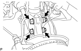
Install the front axle assembly onto the shock absorber with the 2 bolts and 2 nuts.
- Torque:
- 164 N*m { 1672 kgf*cm, 121 ft.*lbf }
Tech Tips
Keep the bolt from rotating while turning the nut.
-
-
INSTALL FRONT LOWER SUSPENSION ARM
-
Install the lower arm onto the steering knuckle with a new castle nut.
- Torque:
- 98 N*m { 999 kgf*cm, 72 ft.*lbf }
Note
If the holes for the clip are not aligned, tighten the nut by a further turn of up to 60°.
-
Install a new clip.
-
-
INSTALL TIE ROD END SUB-ASSEMBLY
-
Install the tie rod end sub-assembly onto the steering knuckle with a new castle nut.
- Torque:
- 49 N*m { 500 kgf*cm, 36 ft.*lbf }
Note
If the holes for the clip are not aligned, tighten the nut by a further turn of up to 60°.
-
Install a new cotter pin.
-
-
INSTALL FRONT STABILIZER LINK ASSEMBLY
-
INSTALL FRONT SPEED SENSOR
-
Install the speed sensor onto the steering knuckle with the bolt.
- Torque:
- 8.5 N*m { 87 kgf*cm, 75 in.*lbf }
Note
-
Check that the speed sensor tip and installation portion are free of foreign matter.
-
Install the speed sensor without turning it from its original installation angle.
-
Install the flexible hose and speed sensor with the bolt.
- Torque:
- 29 N*m { 300 kgf*cm, 22 ft.*lbf }
Note
Install the flexible hose and speed sensor without twisting them.
-
-
INSPECT FRONT AXLE HUB BEARING BACKLASH
-
INSPECT FRONT AXLE HUB RUNOUT
-
INSTALL FRONT DISC
-
INSTALL FRONT DISC BRAKE CALIPER ASSEMBLY
-
Install the disc brake caliper onto the steering knuckle.
- Torque:
- 107 N*m { 1089 kgf*cm, 79 ft.*lbf }
-
-
INSTALL FRONT AXLE SHAFT NUT
-
INSTALL FRONT WHEEL
- Torque:
- 103 N*m { 1050 kgf*cm, 76 ft.*lbf }
-
INSPECT AND ADJUST FRONT WHEEL ALIGNMENT
-
CHECK SPEED SENSOR SIGNAL (w/o VSC)
-
CHECK SPEED SENSOR SIGNAL (w/ VSC)