PARK / NEUTRAL POSITION SWITCH INSTALLATION
PROCEDURE
-
INSTALL PARK/NEUTRAL POSITION SWITCH ASSEMBLY
-
Temporarily install the park/neutral position switch assembly with the 2 bolts.
-
Install the nut and a new nut stopper.
- Torque:
- 6.9 N*m { 70 kgf*cm, 61 in.*lbf }
-
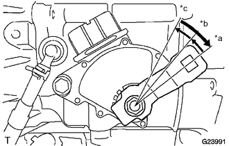
Text in Illustration *a P Position *b R Position *c N Position Temporarily install the transmission control shaft lever, rotate it clockwise until it stops, rotate it counterclockwise for 2 notches to the N position, and then remove the transmission control shaft lever.
-
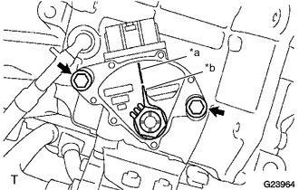
Text in Illustration *a Neutral Reference Line *b Nut Stopper Protrusion Align the neutral reference line with the protrusion on the nut stopper and fully tighten the 2 bolts.
- Torque:
- 5.4 N*m { 55 kgf*cm, 48 in.*lbf }
-
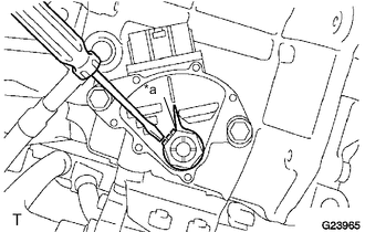
Text in Illustration *a Tabs Bend the tabs of the nut stopper with a screwdriver.
-
Install the transmission control shaft lever and spring washer, and tighten the nut.
- Torque:
- 12 N*m { 122 kgf*cm, 9 ft.*lbf }
-
Connect the park/neutral position switch connector.
-
-
INSTALL TRANSMISSION CONTROL CABLE ASSEMBLY
-
Install the transmission control cable assembly onto the No. 1 transmission control cable bracket with a new clip.
-
Move the shaft lever to N.
-
Install the transmission control cable assembly onto the transmission control shaft lever with the nut.
- Torque:
- 12 N*m { 122 kgf*cm, 9 ft.*lbf }
-
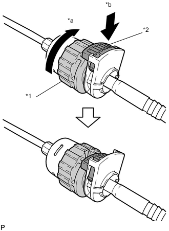
Text in Illustration *1 Nut *2 Lock *a Rotate Approximately 180° *b Push In Rotate the nut of the transmission control cable approximately 180° in the direction shown in the illustration, and while holding the nut, push in the lock.
-
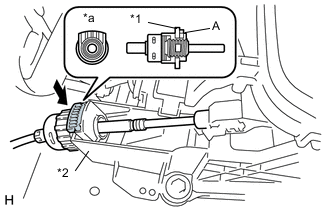
Install the transmission control cable's cable outer to the shift lever assembly.
Text in Illustration *1 Lock *2 Shift Lever Assembly *a Tab Note
-
Install the cable outer with the tab facing upwards.
-
After installation, check that the cable outer lock extends past section A as shown in the diagram.
Tech Tips
As shown in the illustration, the transmission control cable for LHD models passes along the left side of the projection, while the transmission control cable for RHD models passes along the right side of the projection.
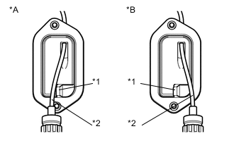
Text in Illustration *A for LHD *B for RHD *1 Projection *2 Transmission Control Cable -
-
Confirm that the shift lever is in N, and then install the cable end to the shift lever assembly.
Note
-
Securely install the cable end to the shift lever assembly.
-
Install the cable end so that its adjustment lock section is on the driver side.
-
-
-
INSTALL BATTERY CARRIER
-
INSTALL BATTERY TRAY
-
INSTALL BATTERY
-
INSPECT SHIFT LEVER POSITION
-
ADJUST SHIFT LEVER POSITION
-
INSTALL REAR CONSOLE BOX