CONTINUOUSLY VARIABLE TRANSAXLE ASSEMBLY REMOVAL

PROCEDURE
-
REMOVE ENGINE ASSEMBLY WITH TRANSAXLE
-
FIX ENGINE ASSEMBLY WITH TRANSAXLE
-
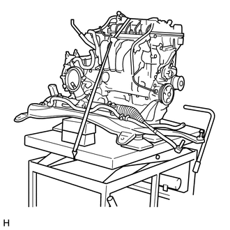
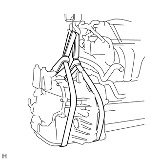
Use a belt with a tightening mechanism or a rope to secure the engine assembly with transaxle to the engine lifter.
Note
-
Do not tighten the belt with a tightening mechanism or the rope any more than is necessary.
-
Set the engine assembly with transaxle so that it is horizontal.
-
-
-
SEPARATE WATER BY-PASS HOSE ASSEMBLY
-
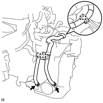
Slide the 2 hose clamps and separate the 2 water by-pass hoses from the oil cooler.
-
Disengage the 2 clamps and separate the water by-pass hoses.
-
-
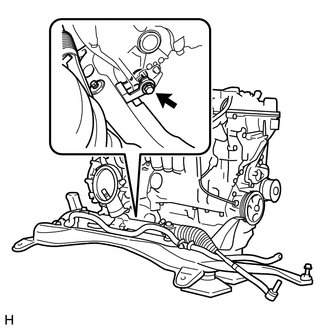
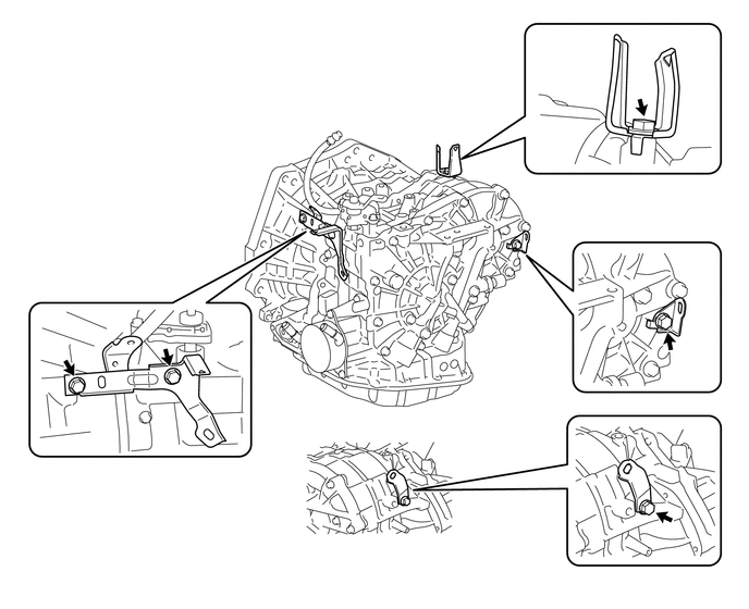
SEPARATE ENGINE WIRE
-
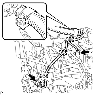
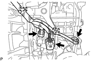
Text in Illustration *1 Oil Pressure Sensor Connector *2 Transmission Revolution Sensor (NOUT) Connector Disconnect the oil pressure sensor connector and revolution sensor connector, and disengage the 4 wire harness clamps from the continuously variable transaxle.
-
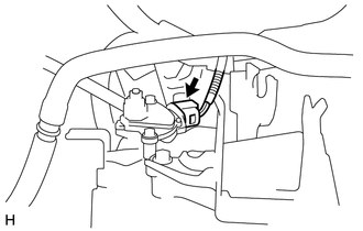
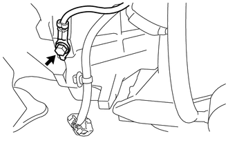
Disconnect the park/neutral position switch connector.
-
Disconnect the transmission wire connector and 2 revolution sensor connectors, and disengage the wire harness clamp, and disengage the 2 wire harness clamps from the continuously variable transaxle.
-
Remove the bolt and engine wire from the continuously variable transaxle.
-
w/ Stop and start system :
-
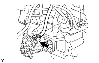
Disconnect the oil pump with motor assembly connector.
-
-
-
REMOVE NO. 1 TRANSMISSION CONTROL CABLE BRACKET
-
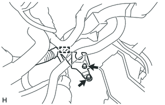
Disengage the clamp and separate the engine wire.
-
Remove the 2 bolts and the No. 1 transmission control cable bracket.
-
-
REMOVE STARTER ASSEMBLY
-
REMOVE DRIVE PLATE AND TORQUE CONVERTER ASSEMBLY SETTING BOLT
-
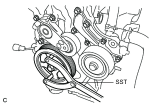
Use SST to hold the crankshaft pulley in place.
- SST
- 09960-10010 ( 09962-01000, 09963-01000 )
-
Remove the 6 drive plate and torque converter assembly setting bolts.
-
-
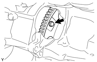
REMOVE FRONT SUSPENSION CROSSMEMBER SUB-ASSEMBLY
-
Remove the bolt and front suspension crossmember sub-assembly.
-
-
REMOVE CONTINUOUSLY VARIABLE TRANSAXLE
-
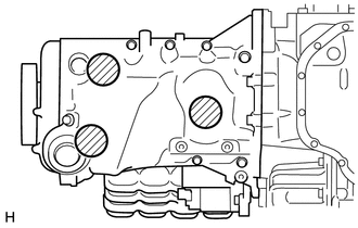
On a flat location, set the attachment, plate lift attachment, and wooden block in the positions shown in the figure, and set the engine assembly with transaxle.
Text in Illustration 
Attachment Placement Positions Note
-
Set the engine assembly with transaxle so that it is horizontal.
-
Never attach the attachment and plate lift attachment to the oil pan section of the continuously variable transaxle.
-
-
Use two belt slings and a mini crane to hold the continuously variable transaxle.
Note
-
Do not lift the engine assembly with transaxle any higher than is necessary.
-
When lifting the engine assembly with transaxle, check the location of the center of gravity while lifting it.
-
-
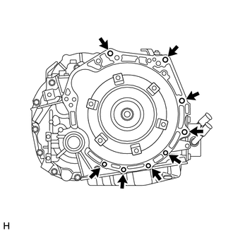
Remove the 8 bolts and continuously variable transaxle from the engine.
Note
To prevent damage to the knock pins, do not pry between the transaxle and engine.
-
-
REMOVE TORQUE CONVERTER ASSEMBLY
-
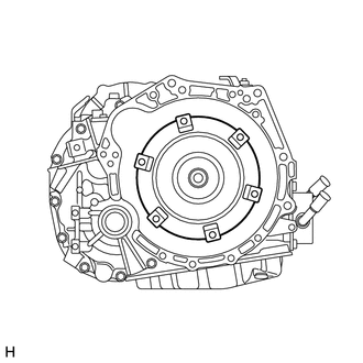
Remove the torque converter assembly from the continuously variable transaxle.
Note
Remove the torque converter assembly from the input shaft horizontally.
-
-
REMOVE CVT OIL PUMP TYPE T OIL SEAL
Note
-
Do not remove the front oil pump assembly from the continuously variable transaxle main body, as there is the possibility of the entry of dust and foreign matter.
-
Clean the work area, the tools to be used, and other equipment, etc. thoroughly before the operation, as there is the possibility that a continuously variable transaxle malfunction, which could prevent the vehicle from running, could occur if dust or fine foreign matter enters the continuously variable transaxle.
-
Do not use cotton work gloves, cloths, or paper towels, etc. that may produce lint, etc.
-
Perform the operation as quickly as possible, as dust and foreign matter could enter the continuously variable transaxle while the torque converter assembly is not attached to it.
-
Do not use the air gun until the torque converter assembly has been installed, as it could cause dust and foreign matter to be stirred up.
-
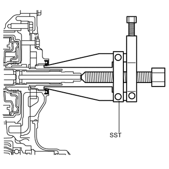
Clean the tips of both the claws and the center bolt of the SST.
-
Using the SST, remove the CVT oil pump type T oil seal.
- SST
- 09308-10010
Note
Pay attention to the angle of the claws when opening them, and ensure that they do not come into contact with the oil pump housing, as there is the possibility that metal particles could be produced if they do.
-
-
REMOVE ENGINE MOVING CONTROL ROD
-
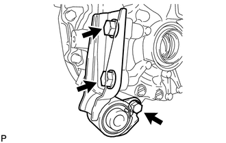
Remove the 3 bolts and the engine moving control rod.
-
-
REMOVE ENGINE MOUNTING BRACKET LH
-
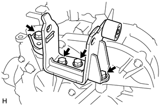
Remove the 4 bolts and the engine mounting bracket LH.
-
-
SEPARATE BREATHER PLUG HOSE
-
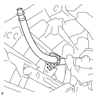
Disengage the clamp and separate the breather plug hose from the wire harness clamp bracket.
-
-
REMOVE WIRE HARNESS CLAMP BRACKET
-
Remove the 5 bolts and the 4 wire harness clamp brackets.
-
-
INSPECT TORQUE CONVERTER ASSEMBLY
-
INSPECT DRIVE PLATE