CONTINUOUSLY VARIABLE TRANSAXLE SYSTEM, Diagnostic DTC:P0705
| DTC Code | DTC Name |
|---|---|
| P0705 | Transmission Range Sensor Circuit Malfunction (PRNDL Input) |
DESCRIPTION
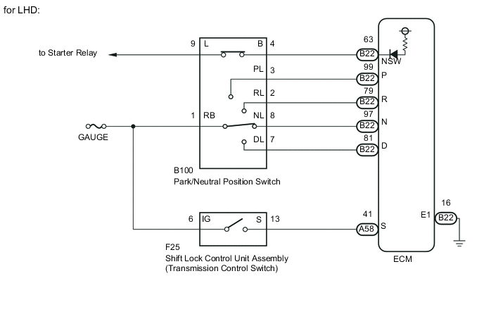
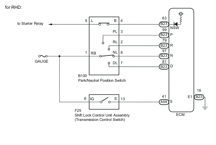
The park/neutral position switch and shift lock control unit assembly (transmission control switch) detect the shift lever position and send signals to the ECM.
| DTC No. | DTC Detection Condition
|
Trouble Area |
|---|---|---|
| P0705 |
|
|
|
||
|
MONITOR DESCRIPTION
For safety, the park/neutral position switch detects the gearshift position so that engine can be started only when the vehicle is in the P or N shift position.
When the park/neutral position switch and shift lock control unit assembly (transmission control switch) send more than one signal at a time from switch positions P, R, N, D, M the ECM interprets this as a fault in the switch. The ECM will turn on the MIL and store the DTC.
WIRING DIAGRAM
CAUTION / NOTICE / HINT
Note
Inspect the fuses for circuits related to this system before performing the following inspection procedure.
PROCEDURE
-
READ VALUE USING INTELLIGENT TESTER (NEUTRAL POSITION SW SIGNAL AND SHIFT SW STATUS)
-
Connect the intelligent tester to the DLC3.
-
Turn the ignition switch to ON.
-
Turn the tester on.
-
Enter the following menus: Powertrain / Engine and ECT / Data List.
-
In accordance with the display on the tester, read the Data List.
Engine and ECT Tester Display Measurement Item/Range Normal Condition Diagnostic Note Neutral Position SW Signal PNP switch status/
OFF or ON
-
OFF: Shift lever not P or N
-
ON: Shift lever in P or N
When shift lever position displayed on intelligent tester differs from actual position, adjustment of PNP switch or shift cable may be incorrect. Shift SW Status (P Range) PNP switch status/
OFF or ON
-
OFF: Shift lever not in P
-
ON: Shift lever in P
Shift SW Status (R Range) PNP switch status/
OFF or ON
-
OFF: Shift lever not in R
-
ON: Shift lever in R
Shift SW Status (N Range) PNP switch status/
OFF or ON
-
OFF: Shift lever not in N
-
ON: Shift lever in N
Shift SW Status (D Range) PNP switch status/
OFF or ON
-
OFF: Shift lever not in D and M
-
ON: Shift lever in D or M
Result Result Proceed to Data display is within Normal Condition range A Data display is not within Normal Condition range B -
B 
CHECK HARNESS AND CONNECTOR (IG1 RELAY - PARK/NEUTRAL POSITION SWITCH) Click here
A 
-
-
READ VALUE USING INTELLIGENT TESTER (SPORTS MODE SELECTION SW)
-
Enter the following menus: Powertrain / Engine and ECT / Data List.
-
In accordance with the display on the tester, read the Data List.
Engine and ECT Tester Display Measurement Item/Range Normal Condition Diagnostic Note Sports Mode Selection SW Sport mode select switch status/
ON or OFF
-
ON: Shift lever in M, "+" or "-"
-
OFF: Shift lever not in M, "+" or "-"
- Result Result Proceed to Data display is within Normal Condition range A Data display is not within Normal Condition range B -
A 
CHECK INTERMITTENT PROBLEMS Click here
B
-
-
INSPECT SHIFT LOCK CONTROL UNIT ASSEMBLY (TRANSMISSION CONTROL SWITCH)
-
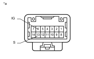
Text in Illustration *a Component without harness connected
(Shift Lock Control Unit Assembly (Transmission Control Switch))
Disconnect the F25 transmission control switch connector of the shift lock control unit assembly.
-
Measure the resistance according to the value(s) in the table below.
Standard Resistance Tester Connection Condition Specified Condition 6 (IG) - 13 (S) Shift lever in M, "+" or "-" Below 1 Ω Shift lever in D 10 kΩ or higher
NG
REPLACE SHIFT LOCK CONTROL UNIT ASSEMBLY Click here
OK
-
-
CHECK HARNESS AND CONNECTOR (IG POWER SUPPLY)
-
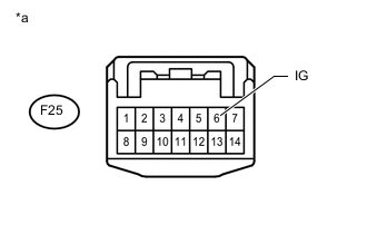
Text in Illustration *a Front view of wire harness connector
(to Shift Lock Control Unit Assembly (Transmission Control Switch))
Turn the ignition switch to ON.
-
Measure the voltage according to the value(s) in the table below.
Standard Voltage Tester Connection Switch Condition Specified Condition F25-6 (IG) - Body ground Ignition switch ON 11 to 14 V
NG
REPAIR OR REPLACE HARNESS OR CONNECTOR
OK
-
-
CHECK HARNESS AND CONNECTOR (TRANSMISSION CONTROL SWITCH - ECM)
-
Disconnect the A58 ECM connector.
-
Measure the resistance according to the value(s) in the table below.
Standard Resistance Tester Connection Condition Specified Condition F25-13 (S) - A58-41 (S) Always Below 1 Ω
NG
REPAIR OR REPLACE HARNESS OR CONNECTOR
OK
-
-
REPLACE ECM
-
Replace the ECM Click here.
NEXT
-
-
PERFORM INITIALIZATION
-
Perform the initialization Click here.
-
Check for DTCs again Click here.
NEXT
END
-
-
CHECK HARNESS AND CONNECTOR (IG1 RELAY - PARK/NEUTRAL POSITION SWITCH)
-
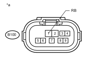
Text in Illustration *a Front view of wire harness connector
(to Park/Neutral Position Switch)
Disconnect the park/neutral position switch connector.
-
Turn the ignition switch to ON.
-
Measure the voltage according to the value(s) in the table below.
Standard Voltage Tester Connection Switch Condition Specified Condition B100-1 (RB) - Body ground Ignition switch ON 11 to 14 V Ignition switch off Below 1 V
NG
REPAIR OR REPLACE HARNESS OR CONNECTOR
OK
-
-
INSPECT PARK/NEUTRAL POSITION SWITCH
-
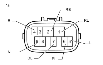
Text in Illustration *a Component without harness connected
(Park/Neutral Position Switch)
Measure the resistance according to the value(s) in the table below.
Standard Resistance Tester Connection Condition Specified Condition 4 (B) - 5 (L) Shift lever in P or N Below 1 Ω Shift lever not in P and N 10 kΩ or higher 2 (RB) - 6 (PL) Shift lever in P Below 1 Ω Shift lever not in P 10 kΩ or higher 1 (RL) - 2 (RB) Shift lever in R Below 1 Ω Shift lever not in R 10 kΩ or higher 2 (RB) - 9 (NL) Shift lever in N Below 1 Ω Shift lever not in N 10 kΩ or higher 2 (RB) - 7 (DL) Shift lever in D or M Below 1 Ω Shift lever not in D and M 10 kΩ or higher
NG
REPLACE PARK/NEUTRAL POSITION SWITCH Click here
OK
-
-
CHECK HARNESS AND CONNECTOR (ECM - PARK/NEUTRAL POSITION SWITCH)
-
Disconnect the B22*1 or B23*2 ECM connectors.
-
*1: for LHD
-
*2: for RHD
-
-
Measure the resistance according to the value(s) in the table below.
Standard Resistance (for LHD) Tester Connection Condition Specified Condition B22-63 (NSW) - B100-4 (B) Always Below 1 Ω B22-99 (P) - B100-3 (PL) Always Below 1 Ω B22-79 (R) - B100-2 (RL) Always Below 1 Ω B22-97 (N) - B100-8 (NL) Always Below 1 Ω B22-81 (D) - B100-7 (DL) Always Below 1 Ω B22-63 (NSW) - Body ground Always 10 kΩ or higher B22-99 (P) - Body ground Always 10 kΩ or higher B22-79 (R) - Body ground Always 10 kΩ or higher B22-97 (N) - Body ground Always 10 kΩ or higher B22-81 (D) - Body ground Always 10 kΩ or higher Standard Resistance (for RHD) Tester Connection Condition Specified Condition B23-63 (NSW) - B100-4 (B) Always Below 1 Ω B23-99 (P) - B100-3 (PL) Always Below 1 Ω B23-79 (R) - B100-2 (RL) Always Below 1 Ω B23-97 (N) - B100-8 (NL) Always Below 1 Ω B23-81 (D) - B100-7 (DL) Always Below 1 Ω B23-63 (NSW) - Body ground Always 10 kΩ or higher B23-99 (P) - Body ground Always 10 kΩ or higher B23-79 (R) - Body ground Always 10 kΩ or higher B23-97 (N) - Body ground Always 10 kΩ or higher B23-81 (D) - Body ground Always 10 kΩ or higher
NG
REPAIR OR REPLACE HARNESS OR CONNECTOR
OK
-
-
REPLACE ECM
-
Replace the ECM Click here.
NEXT
-
-
PERFORM INITIALIZATION
-
Perform the initialization Click here.
-
Check for DTCs again Click here.
NEXT
END
-