CONTINUOUSLY VARIABLE TRANSAXLE SYSTEM Shift Paddle Switch Circuit
DESCRIPTION
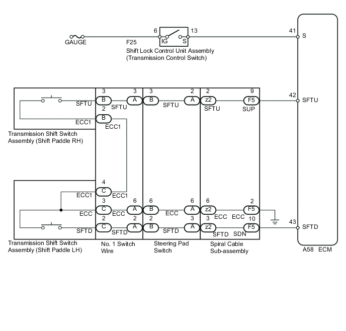
When moving the shift lever into the M position using the transmission control switch, it is possible to switch the shift range position between "1" (first range) and "7" (seventh range). Shifting up "+" once raises one shift range position, and shifting down "-" lowers one shift range position.
WIRING DIAGRAM
CAUTION / NOTICE / HINT
Note
Inspect the fuses for circuits related to this system before performing the following inspection procedure.
PROCEDURE
-
CHECK DTC OUTPUT
-
Connect the intelligent tester to the DLC3.
-
Turn the ignition switch to ON.
-
Turn the tester on.
-
Enter the following menus: Powertrain / Engine and ECT / DTC.
-
Read the DTCs using the tester.
Result Result Proceed to DTCs are not output A DTCs are output B
B 
GO TO DTC CHART Click here
A 
-
-
READ VALUE USING INTELLIGENT TESTER (SPORT MODE SELECTION SW)
-
Enter the following menus: Powertrain / Engine and ECT / Data List.
-
In accordance with the display on the tester, read the Data List.
Engine and ECT Tester Display Measurement Item/Range Normal Condition Diagnostic Note Sports Mode Selection SW Sport mode select switch status/
OFF or ON
OFF: Shift lever not in M, "+" or "-"
ON: Shift lever position; M, "+" or "-"
- Result Result Proceed to Data display is within Normal Condition range A Data display is not within Normal Condition range B
B 
CHECK HARNESS AND CONNECTOR (IG POWER SUPPLY) Click here
A
-
-
READ VALUE USING INTELLIGENT TESTER (SPORT SHIFT UP SW / SPORT SHIFT DOWN SW)
-
Enter the following menus: Powertrain / Engine and ECT / Data List.
-
In accordance with the display on the tester, read the Data List.
Engine and ECT Tester Display Measurement Item/Range Normal Condition Diagnostic Note Sports Shift Up SW Sport shift up switch status/
OFF or ON
OFF: "+" Shift paddle operated and held (up-shift)
ON: "+" Shift paddle operated and held (up-shift)
- Sports Shift Down SW Sport shift down switch status/
OFF or ON
OFF: "-" Shift paddle not operated (down-shift)
ON: "-" Shift paddle operated and held (down-shift)
- Result Result Proceed to Data display is within Normal Condition range A Data display is not within Normal Condition range B
A
CHECK FOR INTERMITTENT PROBLEMS Click here
B
-
-
CHECK HARNESS AND CONNECTOR (TRANSMISSION SHIFT SWITCH - ECM)
-
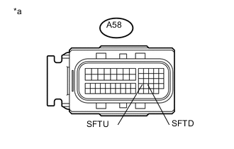
Text in Illustration *a Front view of wire harness connector
(to ECM)
Disconnect the ECM connector.
-
Measure the resistance according to the value(s) in the table below.
Standard Resistance Tester Connection Condition Specified Condition A58-42 (SFTU) - Body ground Pull continuously "+" (up shift) Below 2.5 Ω Release "+" (up shift) 1 MΩ or higher A58-43 (SFTD) - Body ground Pull continuously "-" (down shift) Below 2.5 Ω Release "-" (down shift) 1 MΩ or higher -
Connect the ECM connector.
NG
INSPECT TRANSMISSION SHIFT SWITCH ASSEMBLY Click here
OK
-
-
REPLACE ECM
-
Replace the ECM Click here.
NEXT
-
-
PERFORM INITIALIZATION
-
Perform the initialization Click here.
-
Check for DTCs again Click here.
NEXT
END
-
-
INSPECT TRANSMISSION SHIFT SWITCH ASSEMBLY
-
Remove the steering pad.
-
Disconnect the steering pad switch connector.
-
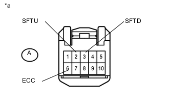
Text in Illustration *a Front view of wire harness connector
(to Steering Pad Switch)
Measure the resistance according to the value(s) in the table below.
Standard Resistance Tester Connection Condition Specified Condition A2 (SFTU) - A6 (ECC) Pull continuously "+" (up shift) Below 2.5 Ω Release "+" (up shift) 1 MΩ or higher A3 (SFTD) - A6 (ECC) Pull continuously "-" (down shift) Below 2.5 Ω Release "-" (down shift) 1 MΩ or higher
NG
INSPECT TRANSMISSION SHIFT SWITCH ASSEMBLY Click here
OK
-
-
INSPECT SPIRAL CABLE SUB-ASSEMBLY
-
Remove the spiral cable sub-assembly.
-
Measure the resistance according to the value(s) in the table below.
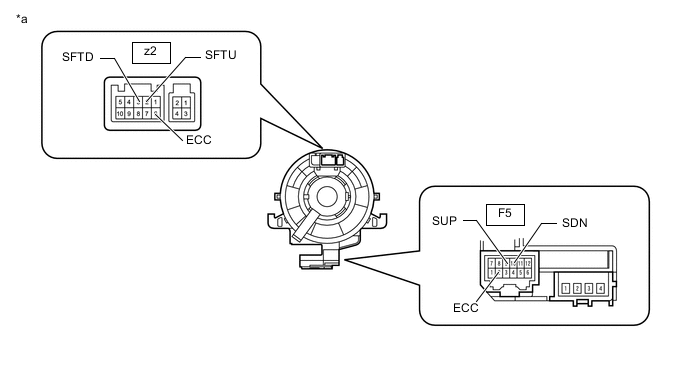
Standard Resistance Tester Connection Condition Specified Condition z2-6 (ECC) - F5-2 (ECC) Always Below 1 Ω z2-2 (SFTU) - F5-9 (SUP) Always Below 1 Ω z2-3 (SFTD) - F5-10 (SDN) Always Below 1 Ω Text in Illustration *a Component without harness connected
(Spiral Cable Sub-assembly)
OK
REPAIR OR REPLACE HARNESS OR CONNECTOR (SPIRAL CABLE - ECM)
NG
REPLACE SPIRAL CABLE SUB-ASSEMBLY Click here
-
-
INSPECT TRANSMISSION SHIFT SWITCH ASSEMBLY
-
Transmission Shift Switch (Shift Paddle Switch RH):
-
Disconnect the transmission shift switch (Shift paddle switch RH) connector.
-
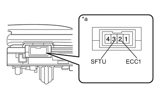
Text in Illustration *a Component without harness connected
(Transmission Shift Switch (Shift Paddle Switch RH)
Measure the resistance according to the value(s) in the table below.
Standard Resistance Tester Connection Condition Specified Condition 3 (SFTU) - 2 (ECC1) Pull continuously "+" (up shift) Below 2.5 Ω Release "+" (up shift) 1 MΩ or higher
-
-
Transmission Shift Switch (Shift Paddle Switch LH):
-
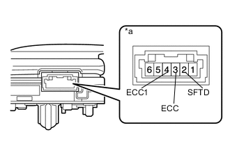
Text in Illustration *a Component without harness connected
(Transmission Shift Switch (Shift Paddle Switch LH)
Disconnect the transmission shift switch (Shift paddle switch LH) connector.
-
Measure the resistance according to the value(s) in the table below.
Standard Resistance Tester Connection Condition Specified Condition 2 (SFTD) - 3 (ECC) Pull continuously "-" (down shift) Below 2.5 Ω Release "-" (down shift) 1 MΩ or higher 3 (ECC) - 4 (ECC1) Always Below 1 Ω
-
NG
REPLACE TRANSMISSION SHIFT SWITCH ASSEMBLY Click here
OK
-
-
INSPECT STEERING PAD SWITCH
-
Disconnect the steering pad switch connector.
-
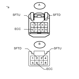
Text in Illustration *a Component without harness connected
(Steering Pad Switch))
Measure the resistance according to the value(s) in the table below.
Standard Resistance Tester Connection Condition Specified Condition A-2 (SFTU) - B-3 (SFTU) Always Below 1 Ω A-3 (SFTD) - B-2 (SFTD) Always Below 1 Ω A-6 (ECC) - B-6 (ECC) Always Below 1 Ω
OK
REPLACE NO. 1 SWITCH WIRE Click here
NG
REPLACE STEERING PAD SWITCH Click here
-
-
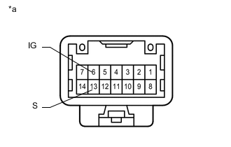
CHECK HARNESS AND CONNECTOR (IG POWER SUPPLY)
-
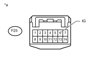
Text in Illustration *a Front view of wire harness connector
(to Shift Lock Control Unit Assembly (Transmission Control Switch))
Turn the ignition switch to ON.
-
Measure the voltage according to the value(s) in the table below.
Standard Voltage Tester Connection Switch Condition Specified Condition F25-6 (IG) - Body ground Ignition switch ON 11 to 14 V
NG
REPAIR OR REPLACE HARNESS OR CONNECTOR
OK
-
-
INSPECT SHIFT LOCK CONTROL UNIT ASSEMBLY (TRANSMISSION CONTROL SWITCH)
-
Text in Illustration *a Component without harness connected
(Shift Lock Control Unit Assembly (Transmission Control Switch))
Disconnect the F25 transmission control switch connector of the shift lock control unit assembly.
-
Measure the resistance according to the value(s) in the table below.
Standard Resistance Tester Connection Condition Specified Condition 6 (IG) - 13 (S) Shift lever in M, "+" or "-" Below 1 Ω Shift lever in D 10 kΩ or higher
NG
REPLACE SHIFT LOCK CONTROL UNIT ASSEMBLY Click here
OK
-
-
CHECK HARNESS AND CONNECTOR (SHIFT LOCK CONTROL UNIT ASSEMBLY - ECM)
-
Disconnect the A58 ECM connector.
-
Measure the resistance according to the value(s) in the table below.
Standard Resistance Tester Connection Condition Specified Condition F25-13 (S) - A58-41 (S) Always Below 1 Ω
NG
REPAIR OR REPLACE HARNESS OR CONNECTOR
OK
-
-
REPLACE ECM
-
Replace the ECM Click here.
NEXT
-
-
PERFORM INITIALIZATION
-
Perform the initialization Click here.
-
Check for DTCs again Click here.
NEXT
END
-