TRANSMISSION CONTROL CABLE INSTALLATION
PROCEDURE
-
INSTALL TRANSMISSION CONTROL CABLE ASSEMBLY
Note
To prevent damage to the transmission control cable assembly and shift lever assembly, connect the continuously variable transaxle assembly side of the transmission control cable assembly before connecting the shift lever assembly side.
-
Install the transmission control cable assembly to the body with the 4 nuts.
- Torque:
- 5.0 N*m { 51 kgf*cm, 44 in.*lbf }
-
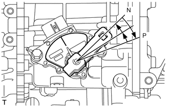
Rotate the transmission control shaft lever clockwise until it stops, and then from that position rotate it counterclockwise by 2 notches to set it to the N position.
-
Install the transmission control cable assembly to the No. 1 transmission control cable bracket with a new clip.
Note
Make sure that the paint mark on the transmission control cable assembly is aligned with the slit in the No. 1 transmission control cable bracket before installing the clip.
-
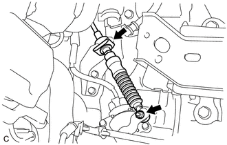
Connect the transmission control cable assembly to the control shaft lever with the nut.
- Torque:
- 12 N*m { 122 kgf*cm, 9 ft.*lbf }
-
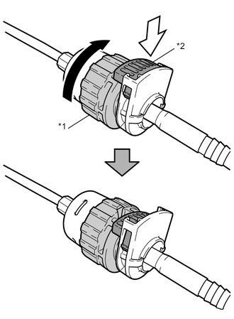
*1 Nut *2 Lock 
Rotate approximately 180° 
Push in Rotate the nut of the transmission control cable assembly approximately 180° in the direction shown in the illustration, and while holding the nut, push in the lock.
Note
Rotating the nut too much will damage the internal spring, and the transmission control cable assembly will not be reusable. Do not turn the nut too far.
-
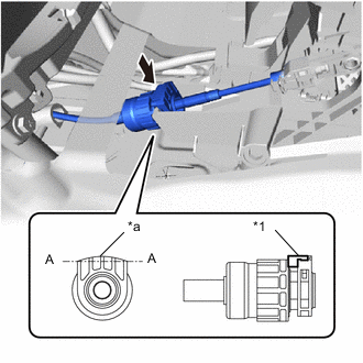
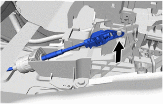
*1 Lock *2 Protrusion Push in Install the transmission control cable assembly to the shift lever assembly.
Note
-
Install the transmission control cable assembly with the protrusion facing upwards.
-
After installation, make sure that the lock is projecting from A as shown in the illustration.
-
Make sure that the transmission control cable assembly is securely locked.
-
-
Confirm that the shift lever is in N, and then connect the end of the transmission control cable assembly to the shift lever assembly.
Note
-
Securely install the end of the transmission control cable assembly to the shift lever assembly.
-
Install the end of the transmission control cable assembly so that its adjustment lock section is on the driver side.
-
-
-
ADJUST SHIFT LEVER POSITION
-
INSTALL FRONT NO. 2 FLOOR HEAT INSULATOR
-
Install the No. 2 floor heat insulator with the 2 bolts and nut.
- Torque:
- 5.5 N*m { 56 kgf*cm, 49 in.*lbf }
-
-
INSTALL FRONT EXHAUST PIPE ASSEMBLY
-
INSTALL REAR CONSOLE BOX ASSEMBLY
-
INSTALL BATTERY CARRIER
-
INSTALL BATTERY TRAY
-
INSTALL BATTERY
-
INSTALL AIR CLEANER CASE SUB-ASSEMBLY
-
INSTALL AIR CLEANER FILTER ELEMENT SUB-ASSEMBLY
-
INSTALL AIR CLEANER CAP SUB-ASSEMBLY
-
INSTALL AIR CLEANER HOSE ASSEMBLY
-
CONNECT NO. 1 AIR HOSE
-
INSTALL NO. 2 VACUUM SWITCHING VALVE ASSEMBLY
-
CONNECT NO. 2 VENTILATION HOSE
-
INSTALL NO. 1 ENGINE COVER
-
CONNECT CABLE TO NEGATIVE BATTERY TERMINAL
- Torque:
- 5.4 N*m { 55 kgf*cm, 48 in.*lbf }
Note
When disconnecting the cable, some systems need to be initialized after the cable is reconnected.
-
INSPECT FOR EXHAUST GAS LEAK
Tech Tips
Perform "Inspection After Repairs" after repairing gas leaks in the exhaust system.
-
INSPECT SHIFT LEVER POSITION