CONTINUOUSLY VARIABLE TRANSAXLE SYSTEM, Diagnostic DTC:P0712, P0713
| DTC Code | DTC Name |
|---|---|
| P0712 | Transmission Fluid Temperature Sensor "A" Circuit Low Input |
| P0713 | Transmission Fluid Temperature Sensor "A" Circuit High Input |
DESCRIPTION
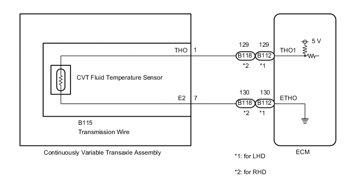
The CVT fluid temperature sensor converts the CVT fluid temperature into a resistance value for use by the ECM.
The sensor resistance changes with the CVT fluid temperature. As the temperature rises, the sensor resistance decreases. The ECM applies voltage to the temperature sensor through ECM terminal THO1 and calculates the fluid temperature based on the voltage signal.
Tech Tips
The CVT fluid temperature is likely to increase under conditions such as towing, climbing hills and in traffic.
| DTC No. | Detection Item | DTC Detection Condition | Trouble Area | MIL | Memory |
|---|---|---|---|---|---|
| P0712 | Transmission Fluid Temperature Sensor "A" Circuit Low Input | There is a short in the CVT fluid temperature sensor circuit for 0.5 seconds (1 trip detection logic). |
|
Comes on | DTC stored |
| P0713 | Transmission Fluid Temperature Sensor "A" Circuit High Input | Either one of the following conditions is met (1 trip detection logic):
|
|
Comes on | DTC stored |
MONITOR DESCRIPTION
The CVT fluid temperature sensor converts the CVT fluid temperature to an electrical resistance value. Based on the resistance, the ECM determines the CVT fluid temperature and can detect an open or short in the CVT fluid temperature circuit. If the resistance value of the CVT fluid temperature is less than 79 Ω*1 or more than 156 kΩ*2, the ECM interprets this as a malfunction of the CVT fluid temperature sensor or wiring, illuminates the MIL and stores a DTC.
*1: 150°C (302°F) or more is indicated regardless of the actual CVT fluid temperature.
*2: -40°C (-40°F) is indicated regardless of the actual CVT fluid temperature.
Tech Tips
The CVT fluid temperature can be checked in the Data List.
WIRING DIAGRAM
CAUTION / NOTICE / HINT
Note
-
Perform initialization after replacing any parts related to the continuously variable transaxle system.
-
Check that no DTCs are stored after performing initialization.
PROCEDURE
-
INSPECT TRANSMISSION WIRE (CVT FLUID TEMPERATURE SENSOR)
-
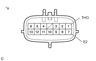
*a Component without harness connected
(Transmission Wire)
Disconnect the B115 transmission wire connector.
-
Measure the resistance according to the value(s) in the table below.
Standard Resistance Tester Connection Condition Specified Condition 1 (THO) - 7 (E2) Always 79 Ω to 156 kΩ 1 (THO) - Body ground and other terminals Always 10 kΩ or higher 7 (E2) - Body ground and other terminals Always 10 kΩ or higher Tech Tips
If the resistance is out of the specified range at any of the CVT fluid temperatures shown in the table below, the driveability of the vehicle may decrease.
CVT Fluid Temperature Specified Condition 10°C (50°F) 5 to 8 kΩ 25°C (77°F) 2.5 to 4.5 kΩ 110°C (230°F) 0.22 to 0.28 kΩ -
Connect the B115 transmission wire connector.
Result Proceed to OK NG
NG 
REPLACE CONTINUOUSLY VARIABLE TRANSAXLE ASSEMBLY Click here
OK 
-
-
CHECK HARNESS AND CONNECTOR (TRANSMISSION WIRE - ECM)
-
Disconnect the B112*1 or B118*2 ECM connector.
-
*1: for LHD
-
*2: for RHD
-
-
Measure the resistance according to the value(s) in the table below.
Standard Resistance (for LHD) Tester Connection Condition Specified Condition B112-129 (THO1) - B112-130 (ETHO) Always 79 Ω to 156 kΩ B112-129 (THO1) - Body ground and other terminals Always 10 kΩ or higher B112-130 (ETHO) - Body ground and other terminals Always 10 kΩ or higher Standard Resistance (for RHD) Tester Connection Condition Specified Condition B118-129 (THO1) - B112-130 (ETHO) Always 79 Ω to 156 kΩ B118-129 (THO1) - Body ground and other terminals Always 10 kΩ or higher B118-130 (ETHO) - Body ground and other terminals Always 10 kΩ or higher -
Connect the B112*1 or B118*2 ECM connector.
-
*1: for LHD
-
*2: for RHD
Result Proceed to OK NG -
NG 
REPAIR OR REPLACE HARNESS OR CONNECTOR
OK
-
-
REPLACE ECM
-
Replace the ECM.
Result Proceed to NEXT
NEXT
PERFORM INITIALIZATION Click here
-
-
REPLACE CONTINUOUSLY VARIABLE TRANSAXLE ASSEMBLY
-
Replace the continuously variable transaxle assembly.
Result Proceed to NEXT
NEXT
PERFORM INITIALIZATION Click here
-