CONTINUOUSLY VARIABLE TRANSAXLE SYSTEM, Diagnostic DTC:P099B, P099C
| DTC Code | DTC Name |
|---|---|
| P099B | Shift Solenoid "G" Control Circuit Low (Shift Solenoid Valve SC) |
| P099C | Shift Solenoid "G" Control Circuit High (Shift Solenoid Valve SC) |
DESCRIPTION
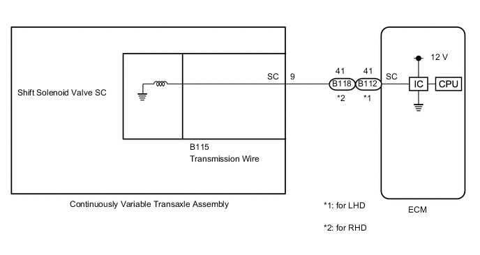
Based on the signal received by the shift solenoid valve SC, the ECM uses the shift solenoid valve SLU to control the forward and reverse clutch pressure.
If there is an open or short in the shift solenoid valve SC circuit, the ECM stops sending current to the malfunctioning shift solenoid valve.
| DTC No. | Detection Item | DTC Detection Condition | Trouble Area | MIL | Memory |
|---|---|---|---|---|---|
| P099B | Shift Solenoid "G" Control Circuit Low (Shift Solenoid Valve SC) | While the vehicle is driven, there is a short in the shift solenoid valve SC circuit for 3 seconds (1 trip detection logic). |
|
Comes on | DTC stored |
| P099C | Shift Solenoid "G" Control Circuit High (Shift Solenoid Valve SC) | While the vehicle is driven, there is an open in the shift solenoid valve SC circuit for 0.5 seconds (1 trip detection logic). |
|
Comes on | DTC stored |
MONITOR DESCRIPTION
These DTCs indicate an open or short in the shift solenoid valve SC circuit. If there is an open or short in the shift solenoid valve SC circuit, the ECM detects the malfunction, illuminates the MIL and stores a DTC.
WIRING DIAGRAM
CAUTION / NOTICE / HINT
Note
-
Perform initialization after replacing any parts related to the continuously variable transaxle system.
-
Check that no DTCs are stored after performing initialization.
PROCEDURE
-
INSPECT TRANSMISSION WIRE (SHIFT SOLENOID VALVE SC)
-
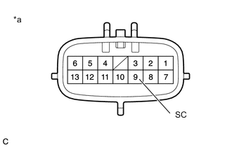
*a Component without harness connected
(Transmission Wire)
Disconnect the B115 transmission wire connector.
-
Measure the resistance according to the value(s) in the table below.
Standard Resistance Tester Connection Condition Specified Condition 9 (SC) - Body ground 20°C (68°F) 11 to 15 Ω -
Connect the B115 transmission wire connector.
Result Proceed to OK NG
NG 
REPLACE CONTINUOUSLY VARIABLE TRANSAXLE ASSEMBLY Click here
OK 
-
-
CHECK HARNESS AND CONNECTOR (TRANSMISSION WIRE - ECM)
-
Disconnect the B112*1 or B118*2 ECM connector.
-
*1: for LHD
-
*2: for RHD
-
-
Measure the resistance according to the value(s) in the table below.
Standard Resistance (for LHD) Tester Connection Condition Specified Condition B112-41 (SC) - Body ground 20°C (68°F) 11 to 15 Ω Standard Resistance (for RHD) Tester Connection Condition Specified Condition B118-41 (SC) - Body ground 20°C (68°F) 11 to 15 Ω -
Connect the B112*1 or B118*2 ECM connector.
-
*1: for LHD
-
*2: for RHD
Result Proceed to OK NG -
NG 
REPAIR OR REPLACE HARNESS OR CONNECTOR
OK
-
-
REPLACE ECM
-
Replace the ECM.
Result Proceed to NEXT
NEXT
PERFORM INITIALIZATION Click here
-
-
REPLACE CONTINUOUSLY VARIABLE TRANSAXLE ASSEMBLY
-
Replace the continuously variable transaxle assembly.
Result Proceed to NEXT
NEXT
PERFORM INITIALIZATION Click here
-