CONTINUOUSLY VARIABLE TRANSAXLE SYSTEM, Diagnostic DTC:P1585
| DTC Code | DTC Name |
|---|---|
| P1585 | Acceleration Sensor Circuit |
DESCRIPTION
The ECM determines the vehicle inclination based on a signal from the airbag ECU assembly (yaw rate and acceleration sensor). If a malfunction of the airbag ECU assembly (yaw rate and acceleration sensor) is determined based on a malfunction signal from the brake actuator assembly (skid control ECU), the ECM stores a DTC.
Tech Tips
-
The airbag ECU assembly (yaw rate and acceleration sensor) signal is sent to the brake actuator assembly (skid control ECU) via CAN communication.
-
If CAN communication DTCs are output, perform troubleshooting for those DTCs first.
| DTC No. | Detection Item | DTC Detection Condition | Trouble Area | MIL | Memory |
|---|---|---|---|---|---|
| P1585 | Acceleration Sensor Circuit | After the ignition switch is turned ON, the brake actuator assembly (skid control ECU) has detected one of the following conditions, and the ECM has received a diagnostic signal from the brake actuator assembly (skid control ECU) for 3 seconds or more (1 trip detection logic).
|
|
Does not come on | DTC stored |
WIRING DIAGRAM
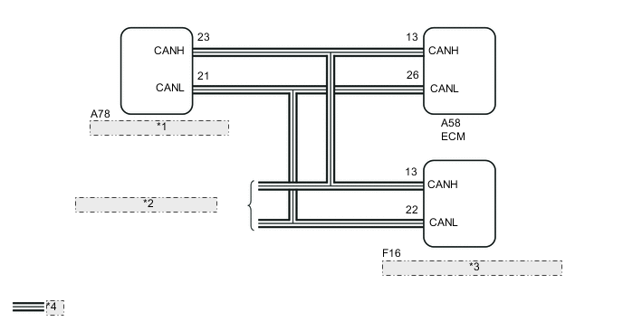
| *1 | Brake Actuator Assembly (Skid Control ECU) |
| *2 | to CAN Communication System |
| *3 | Airbag ECU Assembly (Yaw Rate and Acceleration Sensor) |
| *4 | CAN Communication Line |
CAUTION / NOTICE / HINT
Note
-
Perform initialization after replacing any parts related to the continuously variable transaxle system.
-
Check that no DTCs are stored after performing initialization.
PROCEDURE
-
CHECK DTC OUTPUT
-
Connect the GTS to the DLC3.
-
Turn the ignition switch to ON.
-
Turn the GTS on.
-
Check for DTCs.
Result Result Proceed to DTC U0129 is not output A DTC U0129 is output (w/o Toyota Safety Sense) B DTC U0129 is output (w/ Toyota Safety Sense) C
B 
GO TO CAN COMMUNICATION SYSTEM Click here
C
GO TO CAN COMMUNICATION SYSTEM Click here
A 
-
-
READ VALUE USING GTS (G SENSOR)
-
Connect the GTS to the DLC3.
-
Turn the ignition switch to ON.
-
Turn the GTS on.
-
Enter the following menus: Powertrain / Engine and ECT / Data List.
-
According to the display on the GTS, read the Data List.
Engine and ECT Tester Display Measurement Item Range Normal Condition Diagnostic Note G Sensor Converted output voltage of G sensor Min.: 0 V
Max.: 79.998 V
-
2.31 to 2.69 V: Vehicle on level ground
-
1.88 to 2.5 V: Decelerating
-
2.5 to 3.11 V: Accelerating
-
Stuck at 1.87 V: G sensor malfunction
-
Stuck at 1.87 V: Communication malfunction
- Result Result Proceed to Data List value is not normal A Data List value is normal (for TMMF made LHD) B Data List value is normal (for TMMF made RHD) C -
B
REPLACE BRAKE ACTUATOR ASSEMBLY (SKID CONTROL ECU) Click here
C
REPLACE BRAKE ACTUATOR ASSEMBLY (SKID CONTROL ECU) Click here
A
-
-
REPLACE AIRBAG ECU ASSEMBLY
-
Replace the airbag ECU assembly (yaw rate and acceleration sensor).
Result Proceed to NEXT
NEXT
-
-
PERFORM INITIALIZATION
Result Proceed to NEXT
NEXT
END