| DTC Code | DTC Name |
|---|---|
| P282B | Pressure Control Solenoid "K" Electrical |
DESCRIPTION
According to current from the ECM, the shift solenoid valve SLS controls secondary pulley pressure and belt clamping pressure in accordance with the input shaft torque.
| DTC No. | Detection Item | DTC Detection Condition | Trouble Area | MIL | Memory |
|---|---|---|---|---|---|
| P282B | Pressure Control Solenoid "K" Electrical | While the vehicle is driven, an open or a short is detected in the shift solenoid valve SLS circuit for 1 second or more (1 trip detection logic). |
|
Comes on | DTC stored |
MONITOR DESCRIPTION
This DTC indicates an open or short in the shift solenoid valve SLS circuit. If there is an open or short in the shift solenoid valve SLS circuit, the ECM detects the malfunction, illuminates the MIL and stores this DTC.
CAUTION / NOTICE / HINT
-
Perform initialization after replacing any parts related to the continuously variable transaxle system.
-
Check that no DTCs are stored after performing initialization.
PROCEDURE
- Click here
INSPECT TRANSMISSION WIRE (SHIFT SOLENOID VALVE SLS)
-
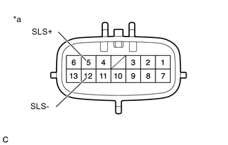
*a Component without harness connected
(Transmission Wire)
Disconnect the B115 transmission wire connector.
-
Measure the resistance according to the value(s) in the table below.
Standard Resistance Tester Connection Condition Specified Condition 5 (SLS+) - 12 (SLS-) 20°C (68°F) 5.0 to 5.6 Ω 5 (SLS+) - Body ground and other terminals Always 10 kΩ or higher 12 (SLS-) - Body ground and other terminals Always 10 kΩ or higher -
Connect the B115 transmission wire connector.
Result Proceed to OK NG
- OKClick here
- NGClick here
-
- Click here
CHECK HARNESS AND CONNECTOR (TRANSMISSION WIRE - ECM)
-
Disconnect the B112*1 or B118*2 ECM connector.
-
*1: for LHD
-
*2: for RHD
-
-
Measure the resistance according to the value(s) in the table below.
Standard Resistance (for LHD) Tester Connection Condition Specified Condition B112-45 (SLS+) - B112-44 (SLS-) 20°C (68°F) 5.0 to 5.6 Ω B112-45 (SLS+) - Body ground and other terminals Always 10 kΩ or higher B112-44 (SLS-) -Body ground and other terminals Always 10 kΩ or higher Standard Resistance (for RHD) Tester Connection Condition Specified Condition B118-45 (SLS+) - B118-44 (SLS-) 20°C (68°F) 5.0 to 5.6 Ω B118-45 (SLS+) - Body ground and other terminals Always 10 kΩ or higher B118-44 (SLS-) -Body ground and other terminals Always 10 kΩ or higher -
Connect the B112*1 or B118*2 ECM connector.
-
*1: for LHD
-
*2: for RHD
Result Proceed to OK NG -
- OKClick here
- NG
REPAIR OR REPLACE HARNESS OR CONNECTOR
-
- Click here
REPLACE ECM
-
Replace the ECM.
Result Proceed to NEXT
- NEXT
PERFORM INITIALIZATIONClick here
-
- Click here
REPLACE CONTINUOUSLY VARIABLE TRANSAXLE ASSEMBLY
-
Replace the continuously variable transaxle assembly.
Result Proceed to NEXT
- NEXT
PERFORM INITIALIZATIONClick here
-