SELECT STROKE SENSOR INSPECTION
PROCEDURE
-
INSPECT SELECT STROKE SENSOR
-
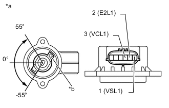
Text in Illustration *a Component without harness connected
(Select Stroke Sensor (Main))
*b Sensor Arm Measure the voltage between the terminals of the select stroke sensor connector (Main).
-
Prepare 3 dry cell batteries (1.5 V) and 2 leads for connecting the batteries and the sensor.
-
Connect the batteries in series.
-
Connect the positive battery terminal to sensor terminal 3 (VCL1), and the negative battery terminal to sensor terminal 2 (E2L1).
-
Measure the voltage according to the value(s) in the table below.
Standard Voltage (combined dry cell battery voltage of 4.5 V) Tester Connection Condition
(Sensor Angle)
Specified Condition 1 (VSL1) - 2 (E2L1) 55° Approximately 4.05 V 0° Approximately 2.25 V -55° Approximately 0.45 V Reference Voltage (combined dry cell battery voltage of 5.0 +/- 0.3 V) Tester Connection Condition
(Sensor Angle)
Specified Condition 1 (VSL1) - 2 (E2L1) 55° Approximately 4.5 V 0° Approximately 2.5 V -55° Approximately 0.5 V Note
-
Do not apply more than 6 V.
-
Do not drop the select stroke sensor. If dropped, replace it with a new one.
If the voltage is not as specified, replace the select stroke sensor.
-
-
-
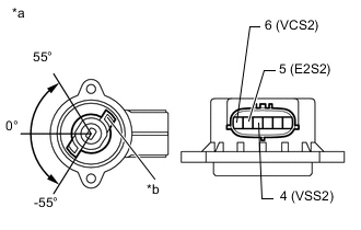
Text in Illustration *a Component without harness connected
(Select Stroke Sensor (Sub))
*b Sensor Arm Measure the voltage between the terminals of the select stroke sensor connector (Sub).
-
Prepare 3 dry cell batteries (1.5 V) and 2 leads for connecting the batteries and the sensor.
-
Connect the batteries in series.
-
Connect the positive battery terminal to sensor terminal 6 (VCL2), and the negative battery terminal to sensor terminal 5 (E2L2).
-
Measure the voltage according to the value(s) in the table below.
Standard Voltage (combined dry cell battery voltage of 4.5 V) Tester Connection Condition
(Sensor Angle)
Specified Condition 4 (VSL2) - 5 (E2L2) 55° Approximately 4.05 V 0° Approximately 2.25 V -55° Approximately 0.45 V Reference Voltage (combined dry cell battery voltage of 5.0 +/- 0.3 V) Tester Connection Condition
(Sensor Angle)
Specified Condition 4 (VSL2) - 5 (E2L2) 55° Approximately 4.5 V 0° Approximately 2.5 V -55° Approximately 0.5 V Note
-
Do not apply more than 6 V.
-
Do not drop the select stroke sensor. If dropped, replace it with a new one.
If the voltage is not as specified, replace the select stroke sensor.
-
-
-