SHIFT STROKE SENSOR INSTALLATION
PROCEDURE
-
INSTALL SHIFT STROKE SENSOR
-
Apply MP grease to a new O-ring and install it to the shift stroke sensor.
-
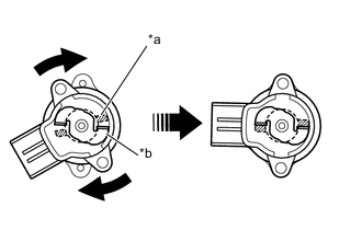
Text in Illustration *a Sensor Arm (Sensor Side) *b Sensor Arm (Actuator Side) Set the shift stroke senor so that the sensor side and the actuator side sensor arms are in the positions shown in the illustration.
-
Turn the shift stroke sensor clockwise and fix it with the 2 screws.
- Torque:
- 1.3 N*m { 13 kgf*cm, 12 in.*lbf }
-
-
INSTALL WIRE HARNESS CLAMP BRACKET
-
Install the wire harness clamp bracket to the shift and select actuator assembly with the bolt.
- Torque:
- 13 N*m { 130 kgf*cm, 9 ft.*lbf }
-
Connect the connectors and install the wire harness clamp.
-
-
INSTALL BATTERY CARRIER
-
INSTALL BATTERY TRAY
-
INSTALL BATTERY
-
INSTALL AIR CLEANER BRACKET
-
INSTALL AIR CLEANER CASE SUB-ASSEMBLY
-
INSTALL AIR CLEANER FILTER ELEMENT SUB-ASSEMBLY
-
INSTALL AIR CLEANER CAP SUB-ASSEMBLY
-
CONNECT CABLE TO NEGATIVE BATTERY TERMINAL
- Torque:
- 5.4 N*m { 55 kgf*cm, 48 in.*lbf }
-
PERFORM INITIALIZATION OF MULTI-MODE MANUAL TRANSAXLE SYSTEM
-
PERFORM LEARNING OF MULTI-MODE MANUAL TRANSAXLE SYSTEM
-
PERFORM SYNCHRONIZATION POSITION CALIBRATION