SHIFT LEVER ASSEMBLY REASSEMBLY
PROCEDURE
-
INSTALL SHIFT LOCK SOLENOID
-
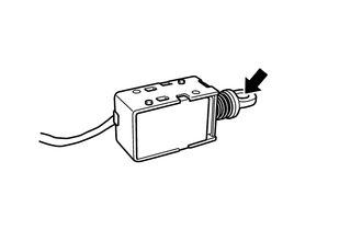
Apply MP grease to the inside of the shift lock solenoid plunger.
Text in Illustration 
MP grease -
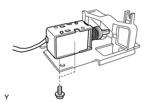
Install the shift lock solenoid to the shift lock unit sub-assembly with the 2 screws.
- Torque:
- 1.7 N*m { 17 kgf*cm, 15 in.*lbf }
-
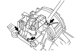
Install the shift lock unit sub-assembly to the shift lock control unit assembly with the 3 screws.
- Torque:
- 1.5 N*m { 15 kgf*cm, 13 in.*lbf }
-
-
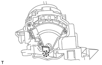
INSTALL SHIFT LEVER POSITION SENSOR
-
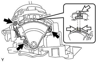
Apply MP grease to the contact surface of the shift lock control unit assembly and the shift lever position sensor.
Text in Illustration 
MP grease -
Install the shift lever position sensor to the shift lock control unit assembly with the 3 screws.
- Torque:
- 1.4 N*m { 14 kgf*cm, 12 in.*lbf }
-
Engage the claw and install the wire harness clamp bracket to the shift lock control unit assembly.
-
-
INSTALL INDICATOR LIGHT WIRE SUB-ASSEMBLY
-
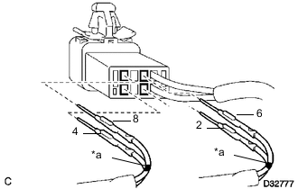
Text in Illustration *a Mark Connect marked wire harnesses 6 and 8 to the indicator light wire connector as shown in the illustration.
-
Connect wire harnesses 2 and 4 to the indicator light wire connector as shown in the illustration.
-
Lock the secondary lock.
-
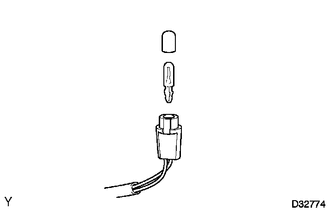
Install the bulb and cap to the indicator light wire sub-assembly.
-
Engage the 3 clamps and install the indicator light wire sub-assembly to the shift lock control unit assembly.
-
-
INSTALL SHIFT LOCK RELEASE BUTTON
-
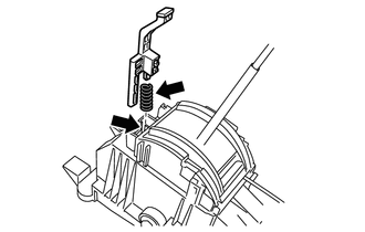
Apply MP grease to the contact surface of the shift lock control unit assembly, the shift lock release button and the compression spring.
Text in Illustration MP grease -
Install the shift lock release button and the compression spring to the shift lock control unit assembly.
-
-
INSTALL POSITION INDICATOR SLIDE COVER
-
Install the position indicator slide cover to the shift lock control unit assembly.
-
-
INSTALL POSITION INDICATOR LIGHT GUIDE
-
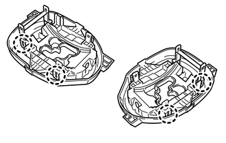
Engage the 4 claws and install the position indicator light guide to the floor shift position indicator housing sub-assembly.
-
-
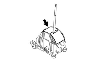
INSTALL FLOOR SHIFT POSITION INDICATOR HOUSING SUB-ASSEMBLY
-
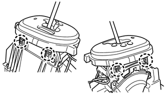
Engage the 4 claws and install the floor shift position indicator housing sub-assembly to the shift lock control unit assembly.
-
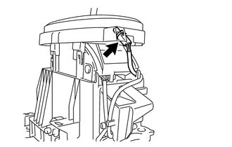
Connect the indicator light wire sub-assembly.
-