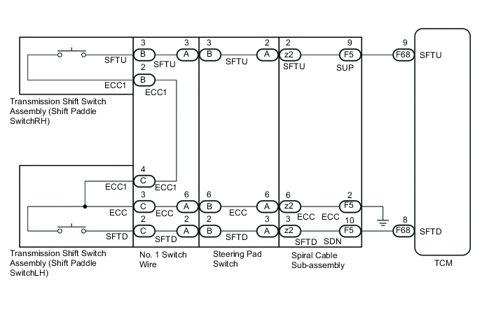
MULTI-MODE MANUAL TRANSAXLE SYSTEM Shift Paddle Switch Circuit
DESCRIPTION
Moving the shift lever to the M or E position enables the gear selection. The drive can select gears optionally by shifting the paddle to the [+] or [-].
WIRING DIAGRAM
PROCEDURE
-
CHECK DTC OUTPUT
-
Connect the intelligent tester to the DLC3.
-
Turn the ignition switch to ON.
-
Turn the tester on.
-
Enter the following menus: Powertrain / Multi-Mode M/T / DTC.
-
Read the DTCs using the tester.
Result Result Proceed to DTCs is not output A DTC is output B
B 
GO TO DTC CHART Click here
A 
-
-
READ VALUE USING INTELLIGENT TESTER (SPORT SHIFT UP SW / SPORT SHIFT DOWN SW)
-
Enter the following menus: Powertrain / Multi-Mode M/T / Data List.
-
In accordance with the display on the tester, read the Data List.
Engine and ECT Tester Display Measurement Item/Range Normal Condition Diagnostic Note Steering SW Signal UP Steering SW Signal UP:
ON or OFF
ON: Pull continuously "+" (Up shift)
OFF: Release "+" (Up shift)
- Steering SW Signal DOWN Steering SW Signal DOWN:
ON or OFF
ON: Pull continuously "-" (Down shift)
OFF: Release "-" (Down shift)
- Result Result Proceed to Data display is within Normal Condition range A Data display is not within Normal Condition range B
A
CHECK FOR INTERMITTENT PROBLEMS Click here
B
-
-
CHECK HARNESS AND CONNECTOR (SHIFT PADDLE SWITCH - TCM)
-
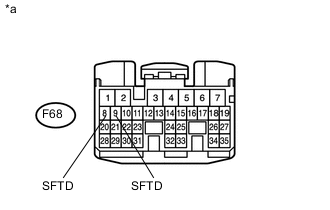
Text in Illustration *a Front view of wire harness connector
(to TCM)
Disconnect the TCM connector.
-
Measure the resistance according to the value(s) in the table below.
Standard Resistance Tester Connection Condition Specified Condition F68-9 (SFTU) - Body ground Pull continuously "+" (up shift) Below 2.5 Ω Release "+" (up shift) 1 MΩ or higher F68-8 (SFTD) - Body ground Pull continuously "-" (down shift) Below 2.5 Ω Release "-" (down shift) 1 MΩ or higher -
Connect the TCM connector.
NG 
CHECK TRANSMISSION SHIFT SWITCH ASSEMBLY Click here
OK
-
-
REPLACE TCM
-
Replace the TCM Click here.
NEXT
-
-
PERFORM INITIALIZATION
-
Perform the initialization and learning for multi-mode manual transaxle system Click here.
NEXT
END
-
-
CHECK TRANSMISSION SHIFT SWITCH ASSEMBLY
-
Remove the steering pad.
-
Disconnect the steering pad switch connector.
-
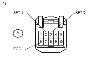
Text in Illustration *a Front view of wire harness connector
(to Steering Pad Switch)
Measure the resistance according to the value(s) in the table below.
Standard Resistance Tester Connection Condition Specified Condition A2 (SFTU) - A6 (ECC) Pull continuously "+" (up shift) Below 2.5 Ω Release "+" (up shift) 1 MΩ or higher A6 (SFTD) - A6 (ECC) Pull continuously "-" (down shift) Below 2.5 Ω Release "-" (down shift) 1 MΩ or higher
NG
INSPECT TRANSMISSION SHIFT SWITCH ASSEMBLY Click here
OK
-
-
INSPECT SPIRAL CABLE SUB-ASSEMBLY
-
Remove the spiral cable sub-assembly.
-
Measure the resistance according to the value(s) in the table below.
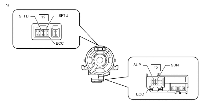
Standard Resistance Tester Connection Condition Specified Condition z2-6 (ECC) - F5-2 (ECC) Always Below 1 Ω z2-2 (SFTU) - F5-9 (SUP) Always Below 1 Ω z2-3 (SFTD) - F5-10 (SDN) Always Below 1 Ω Text in Illustration *a Component without harness connected
(Spiral Cable Sub-assembly)
OK
REPAIR OR REPLACE HARNESS OR CONNECTOR (SHIFT PADDLE SWITCH - TCM)
NG
REPLACE SPIRAL CABLE SUB-ASSEMBLY Click here
-
-
INSPECT TRANSMISSION SHIFT SWITCH ASSEMBLY
-
Transmission Shift Switch (Shift Paddle Switch RH):
-
Disconnect the transmission shift switch (Shift paddle switch RH) connector.
-
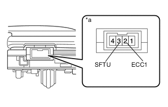
Text in Illustration *a Component without harness connected
(Transmission Shift Switch (Shift Paddle Switch RH))
Measure the resistance according to the value(s) in the table below.
Standard Resistance Tester Connection Condition Specified Condition 3 (SFTU) - 2 (ECC1) Pull continuously "+" (up shift) Below 2.5 Ω Release "+" (up shift) 1 MΩ or higher
-
-
Transmission Shift Switch (Shift Paddle Switch LH):
-
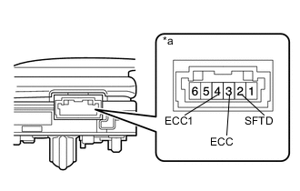
Text in Illustration *a Component without harness connected
(Transmission Shift Switch (Shift Paddle Switch LH))
Disconnect the transmission shift switch (Shift paddle switch LH) connector.
-
Measure the resistance according to the value(s) in the table below.
Standard Resistance Tester Connection Condition Specified Condition 2 (SFTD) - 3 (ECC) Pull continuously "-" (down shift) Below 2.5 Ω Release "-" (down shift) 1 MΩ or higher 3 (ECC) - 4 (ECC1) Always Below 1 Ω
-
NG
REPLACE TRANSMISSION SHIFT SWITCH ASSEMBLY Click here
OK
-
-
INSPECT STEERING PAD SWITCH
-
Disconnect the steering pad switch connector.
-
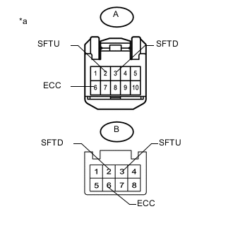
Text in Illustration *a Component without harness connected
(Steering Pad Switch)
Measure the resistance according to the value(s) in the table below.
Standard Resistance Tester Connection Condition Specified Condition A-2 (SFTU) - B-3 (SFTU) Always Below 1 Ω A-3 (SFTD) - B-2 (SFTD) Always Below 1 Ω A-6 (ECC) - B-6 (ECC) Always Below 1 Ω
OK
REPLACE NO. 1 SWITCH WIRE Click here
NG
REPLACE STEERING PAD SWITCH Click here
-