MULTI-MODE MANUAL TRANSAXLE SYSTEM Starter Signal Circuit
DESCRIPTION
-
In this vehicle, the ST relay that supplies power to the starter motor is operated by the cranking holding function of the certification ECU. When the appropriate vehicle conditions are satisfied, the brake pedal is depressed and the transaxle gear is in neutral, the engine can be cranked. If the brake pedal is not depressed or the transaxle gear is not in neutral, the engine cannot be cranked.
During cranking, the ST relay operation signal (STA signal) is input into the STA terminal of the TCM, and is used to control the multi-mode manual transaxle system.
Engine starting control (w/ Entry and Start System)
-
When the ignition switch is turned to ON and the brake pedal is pressed, the TCM turns on the shift lock solenoid in order to release shift lock.
-
When the shift lever is in N, the TCM detects that the shift lever position is in N using the shift position sensor.
-
When the ignition switch is turned to START, the start signal is sent to TCM through the park/neutral position switch. When the TCM receive signal, the starter relay is turned on to cause the engine start.
Engine starting control (w/o Entry and Start System)
WIRING DIAGRAM
Refer to DTC P0617 Click here.
CAUTION / NOTICE / HINT
Tech Tips
If DTC P0703 is output, troubleshoot this code first.
Note
Inspect the fuses for circuits related to this system before performing the following inspection procedure.
PROCEDURE
-
READ VALUE USING INTELLIGENT TESTER (STA SWITCH SIGNAL)
-
Connect an intelligent tester to the DLC3.
-
Turn the ignition switch to ON.
-
Turn the tester on.
-
Enter the following menus: Powertrain / Multi-Mode M/T / Data List / STA Switch Signal.
-
In accordance with the display on the tester, read the Data List.
Tester Display Measurement Item/Range Normal Condition Diagnostic Note STA Switch Signal
[STA SW Sig]
STA signal:
OFF or ON
ON: During cranking - OK [ON] displays in the STA Switch Signal during cranking.
OK 
PROCEED TO NEXT SUSPECTED AREA SHOWN IN PROBLEM SYMPTOMS TABLE Click here
NG 
-
-
CHECK ST RELAY (POWER SOURCE)
-
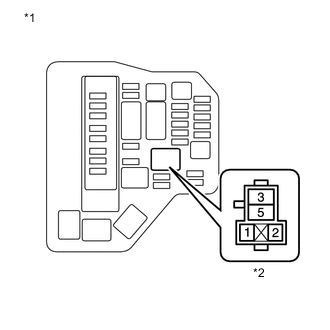
Text In Illustration *1 Engine Room Relay Block *2 ST Relay Holder Remove the ST relay from the engine room relay block.
-
Measure the voltage according to the value(s) in the table below.
Standard Voltage Tester Connection Condition Specified Condition ST relay terminal 2 - Body ground Engine cranking 11 to 14 V Result Result Proceed to OK A NG (w/o Entry and Start System) B NG (w/ Entry and Start System) C
B 
CHECK HARNESS AND CONNECTOR (ST RELAY - TCM) Click here
C
CHECK HARNESS AND CONNECTOR (ST RELAY - PARK/NEUTRAL POSITION SWITCH ASSEMBLY) Click here
A
-
-
INSPECT ST RELAY
-
Inspect the ST relay Click here.
NG
REPLACE ST RELAY
OK
-
-
CHECK HARNESS AND CONNECTOR (ST RELAY - BODY GROUND)
-
Measure the resistance according to the value(s) in the table below.
Standard Resistance Tester Connection Condition Specified Condition ST relay terminal 2 - Body ground Always Below 1 Ω
OK
REPAIR OR REPLACE HARNESS OR CONNECTOR (ECM - TCM)
NG
REPAIR OR REPLACE HARNESS OR CONNECTOR
-
-
CHECK HARNESS AND CONNECTOR (ST RELAY - TCM)
-
Disconnect the TCM connector.
-
Measure the resistance according to the value(s) in the table below.
Standard Resistance Tester Connection Condition Specified Condition ST relay terminal 2 - A47-4 (STRL) Always Below 1 Ω ST relay terminal 2 - A47-6 (STA) Always Below 1 Ω ST relay terminal 2 or A47-4 (STRL) - Body ground Always 10 kΩ or higher ST relay terminal 2 or A47-6 (STA) - Body ground Always 10 kΩ or higher
NG
REPAIR OR REPLACE HARNESS OR CONNECTOR
OK
-
-
CHECK TCM (TMN VOLTAGE)
-
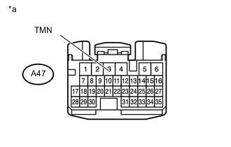
Text In Illustration *a Front view of wire harness connector
(to TCM)
Measure the voltage according to the value(s) in the table below.
Standard Voltage Tester Connection Condition Specified Condition A47-3 (TMN) - Body ground Engine cranking 11 to 14 V
NG
CHECK HARNESS AND CONNECTOR (TCM - PARK/NEUTRAL POSITION SWITCH) Click here
OK
-
-
REPLACE TCM
-
Replace the TCM Click here.
NEXT
-
-
PERFORM INITIALIZATION
-
Perform the initialization and learning for multi-mode manual transaxle system Click here.
NEXT
END
-
-
CHECK HARNESS AND CONNECTOR (TCM - PARK/NEUTRAL POSITION SWITCH)
-
Disconnect the park/neutral position switch assembly connector.
-
Measure the resistance according to the value(s) in the table below.
Standard Resistance Tester Connection Condition Specified Condition A47-3 (TMN) - E2-1 Always Below 1 Ω A47-3 (TMN) or E2-1 - Body ground Always 10 kΩ or higher
NG
REPAIR OR REPLACE HARNESS OR CONNECTOR
OK
-
-
INSPECT PARK/NEUTRAL POSITION SWITCH ASSEMBLY
-
Inspect the park/neutral position switch assembly Click here.
NG
REPLACE PARK/NEUTRAL POSITION SWITCH ASSEMBLY Click here
OK
-
-
CHECK HARNESS AND CONNECTOR (PARK/NEUTRAL POSITION SWITCH - IGNITION SWITCH)
-
Disconnect the ignition switch assembly connector.
-
Measure the resistance according to the value(s) in the table below.
Standard Resistance Tester Connection Condition Specified Condition E2-2 - F13-7 (ST2) Always Below 1 Ω E2-2 or F13-7 (ST2) - Body ground Always 10 kΩ or higher
NG
REPAIR OR REPLACE HARNESS OR CONNECTOR
OK
-
-
INSPECT IGNITION SWITCH ASSEMBLY
-
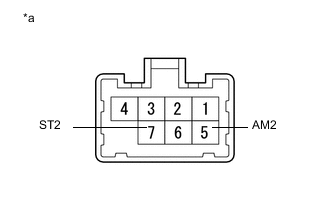
Text In Illustration *a Component without harness connected
(Ignition Switch Assembly)
Measure the resistance according to the value(s) in the table below.
Standard Resistance Tester Connection Switch Condition Specified Condition All terminals LOCK 10 kΩ or higher 5 (AM2) - 7 (ST2) START Below 1 Ω
OK
REPAIR OR REPLACE HARNESS OR CONNECTOR (IGNITION SWITCH ASSEMBLY - BATTERY)
NG
REPLACE IGNITION SWITCH ASSEMBLY Click here
-
-
CHECK HARNESS AND CONNECTOR (ST RELAY - PARK/NEUTRAL POSITION SWITCH ASSEMBLY)
-
Disconnect the park/neutral position switch assembly connector.
-
Measure the resistance according to the value(s) in the table below.
Standard Resistance Tester Connection Switch Condition Specified Condition ST relay terminal 2 - E2- 1 Always Below 1 Ω ST relay terminal 2 or E2-1 - Body ground Always 10 kΩ or higher
NG
REPAIR OR REPLACE HARNESS OR CONNECTOR
OK
-
-
INSPECT PARK/NEUTRAL POSITION SWITCH ASSEMBLY
-
Inspect the park/neutral position switch assembly Click here.
NG
REPLACE PARK/NEUTRAL POSITION SWITCH ASSEMBLY Click here
OK
-
-
CHECK HARNESS AND CONNECTOR (PARK/NEUTRAL POSITION SWITCH ASSEMBLY - CERTIFICATION ECU)
-
Disconnect the certification ECU (smart key ECU assembly) connector.
-
Measure the resistance according to the value(s) in the table below.
Standard Resistance Tester Connection Switch Condition Specified Condition E2-2 - F65-5 (STAR) Always Below 1 Ω E2-2 or F65-5 (STAR) - Body ground Always 10 kΩ or higher
OK
REPLACE CERTIFICATION ECU (SMART KEY ECU ASSEMBLY)
NG
REPAIR OR REPLACE HARNESS OR CONNECTOR
-