MULTI-MODE MANUAL TRANSAXLE ASSEMBLY REMOVAL
PROCEDURE
-
PRECAUTION
CAUTION:
Some of these service operations affect the multi-mode manual transaxle system. Read the precautionary notices concerning the multi-mode manual transaxle system before servicing Click here.
Note
-
When the transaxle is removed, be sure to use a new clutch release cylinder with bearing assembly and new installation bolts. Removal of the transaxle allows the compressed clutch release cylinder with bearing assembly to return to its original position, and dust from the moving section could damage the seal of the clutch release cylinder with bearing assembly, possibly causing clutch fluid leaks.
-
After turning the ignition switch off, waiting time may be required before disconnecting the cable from the battery terminal. Therefore, make sure to read the disconnecting the cable from the battery terminal notice before proceeding with work Click here.
-
-
PLACE FRONT WHEELS FACING STRAIGHT AHEAD
-
DISCONNECT CABLE FROM NEGATIVE BATTERY TERMINAL
-
REMOVE AIR CLEANER CAP SUB-ASSEMBLY
-
REMOVE AIR CLEANER FILTER ELEMENT SUB-ASSEMBLY
-
REMOVE AIR CLEANER CASE SUB-ASSEMBLY
-
REMOVE AIR CLEANER BRACKET
-
REMOVE BATTERY
-
REMOVE BATTERY TRAY
-
REMOVE BATTERY CARRIER
-
REMOVE NO. 2 AIR HOSE
-
REMOVE NO. 1 AIR TUBE
-
REMOVE COLUMN HOLE COVER SILENCER SHEET
-
SEPARATE STEERING SLIDING YOKE SUB-ASSEMBLY
-
SEPARATE NO. 1 STEERING COLUMN HOLE COVER SUB-ASSEMBLY
-
REMOVE CENTER ENGINE UNDER COVER
-
REMOVE ENGINE UNDER COVER LH
-
REMOVE ENGINE UNDER COVER RH
-
DRAIN MANUAL TRANSAXLE OIL
-
REMOVE CLUTCH ACTUATOR ASSEMBLY
Note
-
If the clutch actuator assembly is removed from the multi-mode manual transaxle assembly, perform Learning of Multi-mode Manual Transaxle System.
-
When Learning of Multi-mode Manual Transaxle System is performed, the clutch disc assembly and clutch cover assembly have to be replaced as a set.
-
-
DISCONNECT WIRE HARNESS
-
Remove the bolt and disconnect the wire harness from the manual transaxle assembly.
-
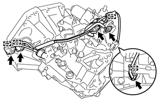
Disconnect the 5 connectors and disengage the 4 wire harness clamps.
-
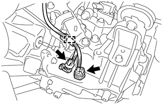
Disconnect the back-up light switch connector and the transmission revolution sensor connector, and disengage the wire harness clamp.
-
Disconnect the 2 shift and select actuator connectors.
-
-
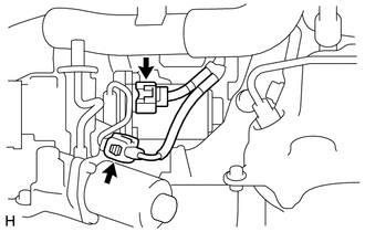
REMOVE STARTER ASSEMBLY (except Cold Area Specification Vehicles)
-
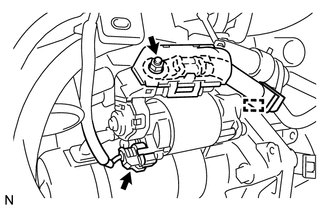
Open the terminal cap.
-
Remove the nut and disconnect the terminal 30.
-
Disconnect the connector and disengage the harness clamp.
-
Remove the 2 bolts and the starter assembly.
-
-
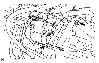
REMOVE STARTER ASSEMBLY (for Cold Area Specification Vehicles)
-
Open the terminal cap.
-
Remove the nut and disconnect the terminal 30.
-
Disconnect the connector and disengage the harness clamp.
-
Remove the 2 bolts and the starter assembly.
-
-
REMOVE FRONT DRIVE SHAFT ASSEMBLIES
-
REMOVE EXHAUST PIPE
-
REMOVE OIL PAN COVER
-
SUPPORT ENGINE ASSEMBLY
-
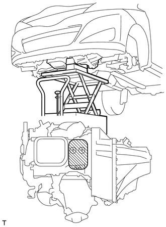
Support the engine assembly with an engine lifter so that it is stable shown in the illustration.
Text in Illustration 
Attachment Placement Positions
-
-
REMOVE FRONT SUSPENSION CROSSMEMBER SUB-ASSEMBLY
-
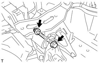
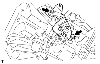
REMOVE ENGINE MOVING CONTROL ROD BRACKET
-
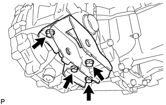
Remove the 4 bolts and the engine moving control rod bracket from the manual transaxle assembly.
-
-
SUPPORT MANUAL TRANSAXLE ASSEMBLY
-
Support the manual transaxle assembly with a transmission jack so that it is stable.
-
-
REMOVE ENGINE MOUNTING INSULATOR LH
-
Remove the bolt and nut, and separate the engine mounting insulator LH from the engine mounting bracket sub-assembly LH.
Note
Turn the bolt while holding the nut.
-
Remove the 5 bolts and the engine mounting insulator LH.
-
-
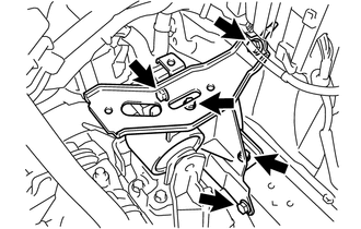
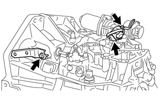
REMOVE ENGINE MOUNTING BRACKET SUB-ASSEMBLY LH
-
Remove the 4 bolts and the engine mounting bracket sub-assembly LH from the manual transaxle assembly.
-
-
REMOVE MANUAL TRANSAXLE ASSEMBLY
-
Operate the engine lifter and transmission jack, and slowly tilt the engine assembly with transaxle.
Note
-
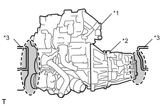
Do not allow the engine and transaxle to interfere with the vehicle body.
Text in Illustration *1 Engine Assembly *2 Manual Transaxle Assembly *3 Vehicle Body 
Watch for Interference -
Do not tilt the engine more than necessary.
-
Do not allow wire harnesses and hoses to be pulled taut.
-
-
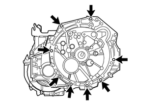
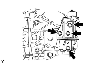
Remove the 8 bolts.
-
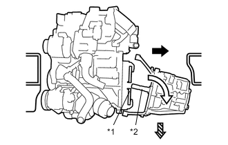
Text in Illustration *1 Clutch Disc *2 Input Shaft 
Move the transaxle towards the left side of the vehicle and disengage the input shaft from the clutch disc. 
Tilt the transaxle and pull the input shaft out from the clutch disc. 
Lower the transaxle. Following the procedures shown in the illustration, remove the manual transaxle assembly.
Note
-
To avoid damage to the knock pins, do not pry between the transaxle and the engine.
-
To avoid damage to the input shaft, do not forcefully shake the transaxle.
-
Do not allow the engine and transaxle to interfere with the vehicle body.
-
-
-
REMOVE AIR TUBE SUPPORT
-
Remove the 2 bolts and the air tube support from the manual transaxle assembly.
-
-
REMOVE WIRE HARNESS CLAMP BRACKET
-
Disconnect the shift stroke sensor connector.
-
Remove the 2 bolts and the 2 wire harness clamp brackets from the manual transaxle assembly.
-
-
REMOVE SPEEDOMETER DRIVEN HOLE COVER SUB-ASSEMBLY
-
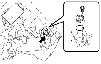
Remove the bolt and the speedometer driven hole cover sub-assembly from the manual transaxle assembly.
-
Remove the O-ring from the speedometer driven hole cover sub-assembly.
-
-
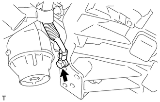
REMOVE CLUTCH RELEASE BLEEDER SUB-ASSEMBLY
-
REMOVE CLUTCH TUBE BOOT
-
REMOVE CLUTCH RELEASE CYLINDER WITH BEARING ASSEMBLY
-
REMOVE CLUTCH RELEASE CYLINDER TO BLEEDER TUBE