OUTPUT SHAFT INSPECTION

PROCEDURE
-
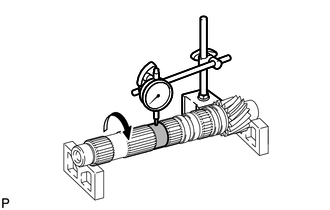
INSPECT 1ST GEAR THRUST CLEARANCE
-
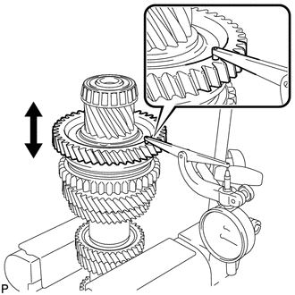
Using a dial indicator, measure the 1st gear thrust clearance.
Standard clearance 0.20 to 0.38 mm (0.00787 to 0.0150 in.) Maximum clearance 0.38 mm (0.0150 in.) If the clearance exceeds the maximum, replace the No. 1 transmission clutch hub, 1st gear bush or 1st gear.
-
-
INSPECT 2ND GEAR THRUST CLEARANCE
-
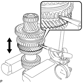
Using a dial indicator, measure the 2nd gear thrust clearance.
Standard clearance 0.15 to 0.33 mm (0.00591 to 0.0130 in.) Maximum clearance 0.33 mm (0.0130 in.) If the clearance exceeds the maximum, replace the inner 2nd gear bearing race, No. 1 transmission clutch hub, 2nd gear or 3rd driven gear.
-
-
INSPECT 1ST GEAR RADIAL CLEARANCE
-
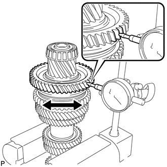
Using a dial indicator, measure the 1st gear radial clearance.
Standard clearance 0.009 to 0.045 mm (0.000354 to 0.00177 in.) Maximum clearance 0.045 mm (0.00177 in.) If the clearance exceeds the maximum, replace the 1st gear, 1st gear needle roller bearing or output shaft.
-
-
INSPECT 2ND GEAR RADIAL CLEARANCE
-
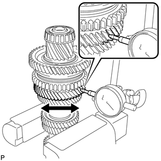
Using a dial indicator, measure the 2nd gear radial clearance.
Standard clearance 0.009 to 0.045 mm (0.000354 to 0.00177 in.) Maximum clearance 0.045 mm (0.00177 in.) If the clearance exceeds the maximum, replace the 2nd gear, 2nd gear needle roller bearing or output shaft.
-
-
INSPECT OUTPUT SHAFT
-
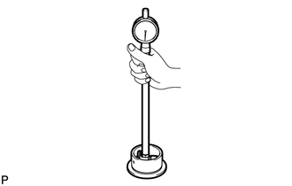
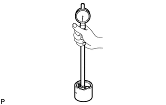
Using a dial indicator and 2 V-blocks, check the output shaft runout.
Maximum runout 0.015 mm (0.000591 in.) If the runout exceeds the maximum, replace the output shaft.
-
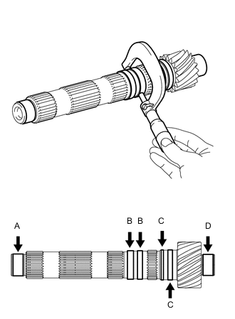
Using a micrometer, measure the outer diameter of the output shaft journal surface at the locations indicated.
Standard outer diameter Part A 30.002 to 30.017 mm (1.1812 to 1.1818 in.) Part B 37.990 to 38.000 mm (1.4957 to 1.4961 in.) Part C 40.790 to 40.800 mm (1.6059 to 1.6063 in.) Part D 28.002 to 28.017 mm (1.1024 to 1.1030 in.) Minimum outer diameter Part A 30.002 mm (1.1812 in.) Part B 37.990 mm (1.4957 in.) Part C 40.790 mm (1.6059 in.) Part D 28.002 mm (1.1024 in.) If any of the outer diameters are less than the minimum, replace the output shaft.
-
-
INSPECT 1ST GEAR
-
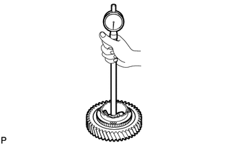
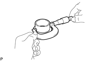
Using a cylinder gauge, measure the inside diameter of the 1st gear.
Standard inside diameter 52.909 to 52.925 mm (2.0830 to 2.0837 in.) Maximum inside diameter 52.925 mm (2.0837 in.) If the inside diameter exceeds the maximum, replace the 1st gear.
-
-
INSPECT 2ND GEAR
-
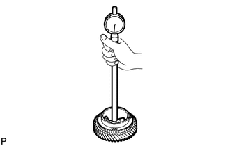
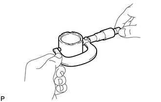
Using a cylinder gauge, measure the inside diameter of the 2nd gear.
Standard inside diameter 52.909 to 52.925 mm (2.0830 to 2.0837 in.) Maximum inside diameter 52.925 mm (2.0837 in.) If the inside diameter exceeds the maximum, replace the 2nd gear.
-
-
INSPECT 1ST GEAR BUSH
-
Using a micrometer, measure the outer diameter of the 1st gear bush.
Standard outer diameter 47.89 to 47.90 mm (1.8854 to 1.8858 in.) Minimum outer diameter 47.89 mm (1.8854 in.) If the outer diameter is less than the minimum, replace the 1st gear bush.
-
Using a cylinder gauge, measure the inside diameter of the 1st gear bush.
Standard inside diameter 40.805 to 40.820 mm (1.6065 to 1.6071 in.) Maximum inside diameter 40.820 mm (1.6071 in.) If the inside diameter exceeds the maximum, replace the 1st gear bush.
-
-
INSPECT INNER 2ND GEAR BEARING RACE
-
Using a micrometer, measure the outer diameter of the inner 2nd gear bearing race.
Standard outer diameter 47.89 to 47.90 mm (1.8854 to 1.8858 in.) Minimum outer diameter 47.89 mm (1.8854 in.) If the outer diameter is less than the minimum, replace the inner 2nd gear bearing race.
-
Using a cylinder gauge, measure the inside diameter of the inner 2nd gear bearing race.
Standard inside diameter 38.005 to 38.020 mm (1.4963 to 1.4968 in.) Maximum inside diameter 38.020 mm (1.4968 in.) If the inside diameter exceeds the maximum, replace the inner 2nd gear bearing race.
-
-
INSPECT NO. 1 SYNCHRONIZER RING SET (FOR 1ST GEAR)
-
Coat the 1st gear cone and No. 1 synchronizer ring set (inner ring, middle ring, and outer ring) with gear oil.
-
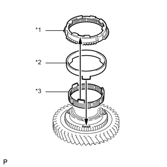
Text in Illustration *1 Outer Ring *2 Middle Ring *3 Inner Ring Install the inner ring to the 1st gear.
-
Install the middle ring to the 1st gear.
-
Install the outer ring to the 1st gear.
-
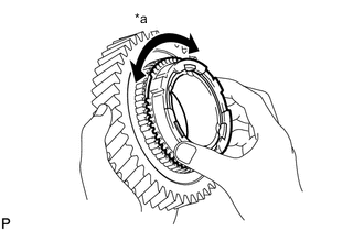
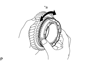
Text in Illustration *a Locks Check for wear and damage.
-
Turn the No. 1 synchronizer ring set in one direction while pushing it against the 1st gear cone.
-
Check that the ring set locks.
If the No. 1 synchronizer ring set does not lock, replace the No. 1 synchronizer ring set.
-
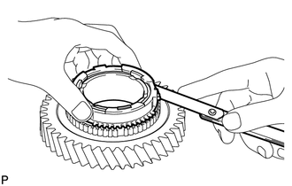
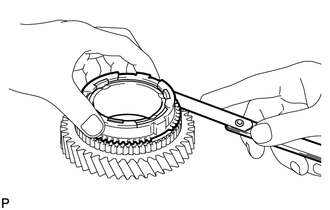
Using a feeler gauge, measure the clearance between the No. 1 synchronizer ring set (outer ring) and gear spline end.
Standard clearance 0.915 to 1.855 mm (0.03602 to 0.07303 in.) Minimum clearance 0.915 mm (0.03602 in.) If the clearance is less than the minimum, replace the No. 1 synchronizer ring set.
-
-
INSPECT NO. 1 SYNCHRONIZER RING SET (FOR 2ND GEAR)
-
Coat the 2nd gear cone and No. 1 synchronizer ring set (inner ring, middle ring, and outer ring) with gear oil.
-
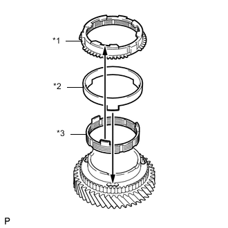
Text in Illustration *1 Outer Ring *2 Middle Ring *3 Inner Ring Install the inner ring to the 2nd gear.
-
Install the middle ring to the 2nd gear.
-
Install the outer ring to the 2nd gear.
-
Text in Illustration *a Locks Check for wear and damage.
-
Turn the No. 1 synchronizer ring set in one direction while pushing it against the 2nd gear cone.
-
Check that the ring set locks.
If the No. 1 synchronizer ring set does not lock, replace the No. 1 synchronizer ring set.
-
Using a feeler gauge, measure the clearance between the No. 1 synchronizer ring set (outer ring) and gear spline end.
Standard clearance 0.92 to 1.86 mm (0.0362 to 0.0732 in.) Minimum clearance 0.92 mm (0.0362 in.) If the clearance is less than the minimum, replace the No. 1 synchronizer ring set.
-
-
INSPECT REVERSE GEAR
-
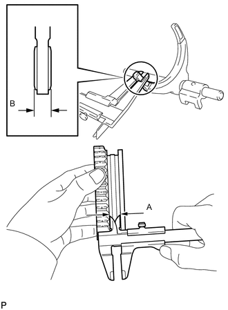
Using a vernier caliper, measure the width of the reverse gear groove (A) and the thickness of the claw part on the No. 1 gear shift fork shaft assembly (B), and calculate the clearance.
Standard clearance (A - B) 0.1 to 0.5 mm (0.00394 to 0.0197 in.) If the clearance is out of specification, replace the reverse gear and No. 1 gear shift fork shaft assembly.
-
-
INSPECT NO. 1 TRANSMISSION CLUTCH HUB
-
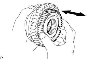
Check that the No. 1 transmission clutch hub and reverse gear slide smoothly.
-
Check that the edges of the reverse gear spline gear are not worn down.
-