MULTI-MODE MANUAL TRANSAXLE SYSTEM, Diagnostic DTC:P0885, P0887
| DTC Code | DTC Name |
|---|---|
| P0885 | TCM Power Relay Control Circuit / Open |
| P0887 | TCM Power Relay Control Circuit (Short) |
DESCRIPTION
The multi-mode manual transaxle system has a dedicated power supply circuit. While the ignition switch is turned to ON, the TCM outputs the power from the MREL terminal to operate the MMT relay. Then, the power is supplied to the +BM terminal of the TCM through the MMT relay. The voltage (+BM) is monitored and when it is low (4.00 V or less) despite the voltage being supplied to the MREL circuit, the TCM determines that there is a malfunction in the multi-mode manual transaxle system and sets a DTC. When the voltage (+BM) is high (4.00 V or more) although the voltage is not supplied to the MREL circuit, the TCM sets a DTC.
| DTC No. | DTC Detecting Condition | Trouble Area |
|---|---|---|
| P0885 | The TCM detects the following conditions simultaneously: (1-trip detection logic)
|
|
| P0887 | The TCM detects the following conditions simultaneously: (1-trip detection logic)
|
|
WIRING DIAGRAM
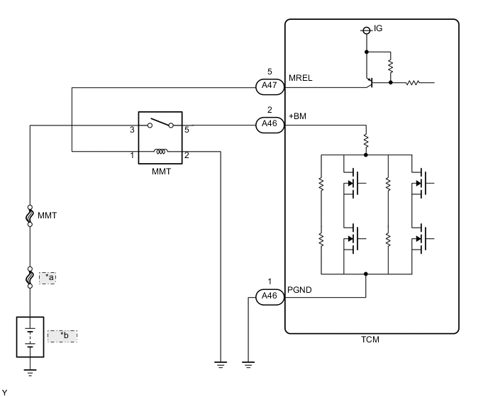
| *a | MAIN |
| *b | Battery |
CAUTION / NOTICE / HINT
Note
Inspect the fuses for circuits related to this system before performing the following inspection procedure.
PROCEDURE
-
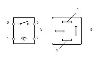
INSPECT MMT RELAY
-
Remove the MMT relay from the engine room relay block.
-
Measure the resistance according to the value(s) in the table below.
Standard Resistance Tester Connection Condition Specified Condition 3 - 5 Battery voltage is not applied 10 kΩ or higher Battery voltage applied to terminals 1 and 2 Below 1 Ω -
Reinstall the MMT relay.
NG 
REPLACE MMT RELAY
OK 
-
-
INSPECT TCM (+BM TERMINAL INPUT VOLTAGE)
-
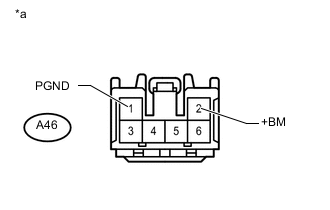
Text In Illustration *a Front view of wire harness connector
(to TCM)
Disconnect the TCM connector.
-
Measure the voltage according to the value(s) in the table below.
Standard Voltage Tester Connection Switch Condition Specified Condition A46-2 (+BM) - A46-1 (PGND) Ignition switch off Below 1 V A46-2 (+BM) - A46-1 (PGND) Ignition switch ON 11 to 14 V Result Result Proceed to NG A OK B
B 
REPLACE TCM Click here
A
-
-
CHECK HARNESS AND CONNECTOR (TCM - BODY GROUND)
-
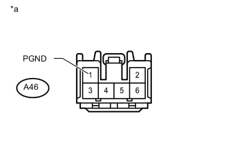
Text In Illustration *a Front view of wire harness connector
(to TCM)
Measure the resistance according to the value(s) in the table below.
Standard Resistance Tester Connection Condition Specified Condition A46-1 (PGND) - Body ground Always Below 1 Ω
NG
REPAIR OR REPLACE HARNESS OR CONNECTOR
OK
-
-
INSPECT TCM (MREL TERMINAL OUTPUT VOLTAGE)
-
Reconnect the TCM connectors.
-
Turn the ignition switch to ON.
-
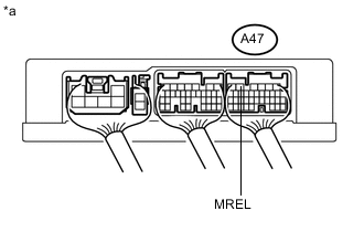
Text In Illustration *a Component with harness connected
(TCM)
Measure the voltage according to the value(s) in the table below.
Standard Voltage Tester Connection Switch Condition Specified Condition A47-5 (MREL) - Body ground Ignition switch off Below 1 V Ignition switch ON 11 to 14 V
NG
REPLACE TCM Click here
OK
-
-
CHECK HARNESS AND CONNECTOR (TCM - MMT RELAY)
-
Disconnect the TCM connectors.
-
Remove the MMT relay from the engine room sub relay block.
-
Measure the resistance according to the value(s) in the table below.
Standard Resistance Tester Connection Condition Specified Condition A47-5 (MREL) - MMT relay (1) Always Below 1 Ω A46-2 (+BM) - MMT relay (5) Always Below 1 Ω A47-5 (MREL) or MMT relay (1) - Body ground Always 10 kΩ or higher A46-2 (+BM) or MMT relay (5) - Body ground Always 10 kΩ or higher
NG
REPAIR OR REPLACE HARNESS OR CONNECTOR
OK
-
-
CHECK HARNESS AND CONNECTOR (BATTERY - MMT RELAY)
-
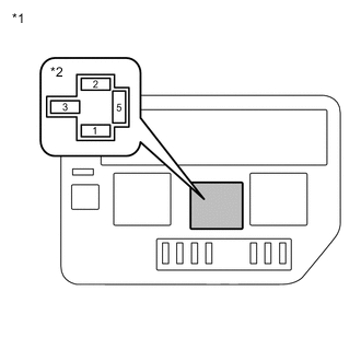
Text In Illustration *1 Engine room sub relay block *2 MMT relay Holder Measure the voltage according to the value(s) in the table below.
Standard Voltage Tester Connection Condition Specified Condition MMT relay (terminal 3) - Body ground Always 11 to 14 V
NG
REPAIR OR REPLACE HARNESS OR CONNECTOR
OK
-
-
CHECK HARNESS AND CONNECTOR (MMT RELAY - BODY GROUND)
-
Measure the resistance according to the value(s) in the table below.
Standard Resistance Tester Connection Condition Specified Condition MMT relay (terminal 2) -Body ground Always Below 1 Ω
NG
REPAIR OR REPLACE HARNESS OR CONNECTOR
OK
-
-
REPLACE TCM
-
Replace the TCM Click here.
NEXT
-
-
PERFORM INITIALIZATION
-
Perform the initialization and learning for multi-mode manual transaxle system Click here.
NEXT
END
-