SHIFT AND SELECT LEVER SHAFT REASSEMBLY
PROCEDURE
-
INSTALL SELECT STOPPER BLOCK
-
Coat the select stopper block with manual transaxle oil.
-
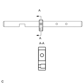
Make sure that the select stopper block is installed as shown in the illustration.
Note
Make sure of the installation direction.
-
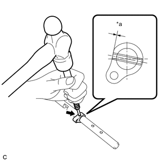
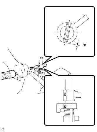
Text in Illustration *a Depth Using a pin punch 5 mm and a hammer, install the slotted spring pin onto the shift and select lever shaft.
Driven in depth -0.2 to 0.8 mm (-0.00787 to 0.0315 in.)
-
-
INSTALL RELEASE HEAD STRAIGHT PIN
-
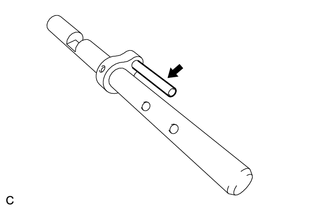
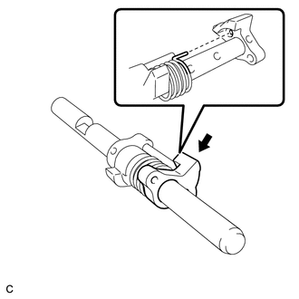
Install the release head straight pin to the select stopper block.
-
Coat the release head with manual transaxle oil.
-
Make sure that the release head is installed as shown in the illustration.
Note
Make sure of the installation direction.
-
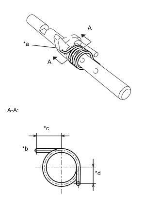
Text in Illustration *a Hook *b Hook Side *c 14.5 to 15.5 mm (0.571 to 0.610 in.) *d 8.3 to 9.3 mm (0.327 to 0.366 in.) Make sure that the release head torsion spring is installed as shown in the illustration.
Note
Make sure of the installation direction.
-
Coat the front inner shift lever with manual transaxle oil.
-
Make sure that the front inner shift lever is installed as shown in the illustration.
Note
Make sure of the installation direction.
Tech Tips
Insert the torsion spring to the installation hole of the front inner shift lever.
-
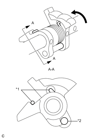
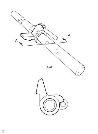
Text in Illustration *1 Release Head Torsion Spring *2 Release Head Straight pin Turn the front inner shift lever counterclockwise to align it with the installation surface of the release head straight pin, and install it.
Note
Make sure that the front shift lever is installed as shown in the illustration.
-
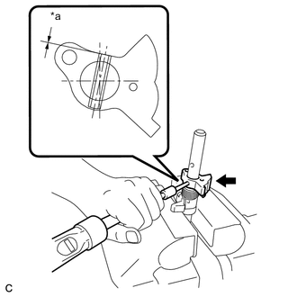
Text in Illustration *a Depth Using a pin punch 5 mm and a hammer, install the slotted spring pin onto the shift and select lever shaft.
Driven in depth -0.2 to 0.8 mm (-0.00787 to 0.0315 in.)
-
-
INSTALL INNER NO. 2 SHIFT LEVER
-
Coat the inner No. 2 shift lever with manual transaxle oil.
-
Text in Illustration *a Depth Using a pin punch 5 mm and a hammer, install the inner No. 2 shift lever and slotted spring pin onto the shift and select lever shaft.
Driven in depth 0 to 0.6 mm (0 to 0.0236 in.) Note
Make sure of the installation direction.
-