MANUAL TRANSAXLE UNIT REASSEMBLY

PROCEDURE
-
INSTALL FRONT DIFFERENTIAL CASE FRONT TAPERED ROLLER BEARING
-
for 2NR-FKE:
-
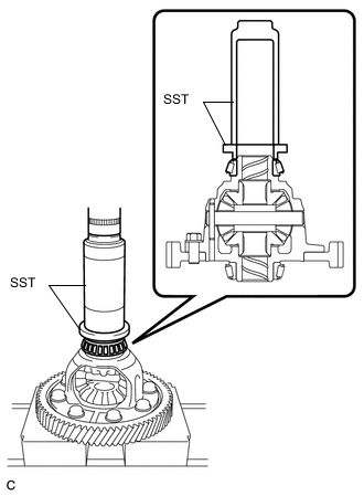
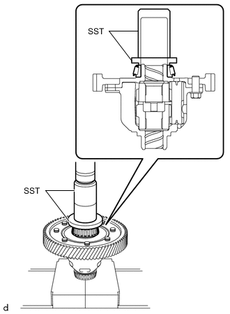
Using SST and a press, install a new front differential case front tapered roller bearing to the differential case assembly.
- SST
- 09309-37010
- 09506-35010
-
-
for 2ZR-FE:
-
Using SST and a press, install a new front differential case front tapered roller bearing to the differential case assembly.
- SST
- 09309-37010
- 09506-35010
-
-
Using SST and a press, install a new front differential case front tapered roller bearing (outer race) together with the front differential case front plate washer to the front transaxle case.
- SST
- 09950-60021 ( 09951-00680 )
- 09950-70010 ( 09951-07200 )
-
-
INSTALL FRONT DIFFERENTIAL CASE REAR TAPERED ROLLER BEARING
-
for 2NR-FKE:
-
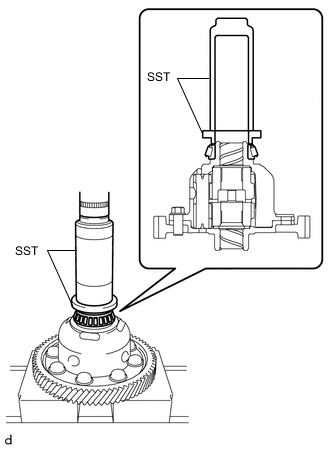
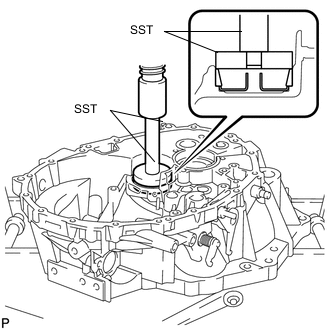
Using SST and a press, install a new front differential case rear tapered roller bearing to the differential case assembly.
- SST
- 09636-20010
- 09726-40010
-
-
for 2ZR-FE:
-
Using SST and a press, install a new front differential case rear tapered roller bearing to the differential case assembly.
- SST
- 09636-20010
- 09726-40010
-
-
Using SST and a press, install a new front differential case rear tapered roller bearing (outer race) together with the front differential case rear plate washer to the manual transmission case.
- SST
- 09309-36010
- 09950-60021 ( 09951-00730 )
- 09950-70010 ( 09951-07100 )
Tech Tips
Use a front differential case rear plate washer of the same thickness as the removed one.
-
-
ADJUST DIFFERENTIAL SIDE BEARING PRELOAD (for 2NR-FKE)
-
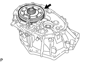
Coat the differential case assembly with gear oil and install it to the front transaxle case.
-
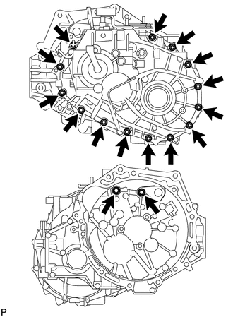
Install the manual transmission case to the front transaxle case with the 16 bolts.
- Torque:
- 29.4 N*m { 300 kgf*cm, 22 ft.*lbf }
-
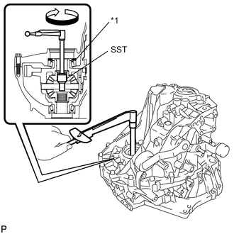
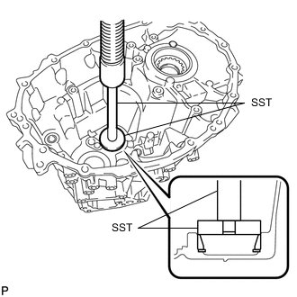
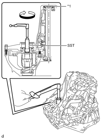
*1 Front Differential Case Rear Plate Washer Using SST and a torque wrench, turn the differential case assembly clockwise and counterclockwise 2 or 3 times to allow the bearings to settle.
- SST
- 09564-32011
-
Using SST and a torque wrench, measure the preload.
- SST
- 09564-32011
Preload (at starting) New bearing 1.0 to 1.6 N*m (10 to 17 kgf*cm, 9 to 14 in.*lbf) Used bearing 0.8 to 1.3 N*m (9 to 13 kgf*cm, 8 to 12 in.*lbf) If the preload is out of specification, select a front differential case rear plate washer.
Front Differential Case Rear Plate Washer Thickness Part No. Mark Thickness
mm (in.)
90564-44039 10 2.100 (0.0827) 90564-44040 11 2.125 (0.0837) 90564-44041 12 2.150 (0.0846) 90564-44042 13 2.175 (0.0856) 90564-44043 14 2.200 (0.0866) 90564-44044 15 2.225 (0.0876) 90564-44045 16 2.250 (0.0886) 90564-44046 17 2.275 (0.0896) 90564-44047 18 2.300 (0.0906) 90564-44048 19 2.325 (0.0915) 90564-44049 20 2.350 (0.0925) 90564-44050 21 2.375 (0.0935) 90564-44051 22 2.400 (0.0945) 90564-44052 23 2.425 (0.0955) 90564-44053 24 2.450 (0.0965) 90564-44054 25 2.475 (0.0974) 90564-44055 26 2.500 (0.0984) 90564-44056 27 2.525 (0.0994) 90564-44057 28 2.550 (0.1004) 90564-44058 29 2.575 (0.1014) 90564-44059 30 2.600 (0.1024) 90564-44060 31 2.625 (0.1033) 90564-44061 32 2.650 (0.1043) 90564-44062 33 2.675 (0.1053) 90564-44063 34 2.700 (0.1063) 90564-44064 35 2.725 (0.1073) 90564-44065 36 2.750 (0.1083) 90564-44066 37 2.775 (0.1093) 90564-44067 38 2.800 (0.1102) 90564-44068 39 2.825 (0.1112) 90564-44069 40 2.850 (0.1122) Tech Tips
-
Select a thicker plate washer to increase the preload or a thinner plate washer to decrease the preload.
-
Make a memo as the torque values will be needed to adjust output shaft bearing preload.
-
Remove the 16 bolts and the manual transmission case from the front transaxle case.
-
Remove the differential case assembly from the front transaxle case.
-
-
ADJUST DIFFERENTIAL SIDE BEARING PRELOAD (for 2ZR-FE)
-
Coat the differential case assembly with gear oil and install it to the front transaxle case.
-
Install the manual transmission case to the front transaxle case with the 16 bolts.
- Torque:
- 29.4 N*m { 300 kgf*cm, 22 ft.*lbf }
-
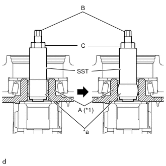
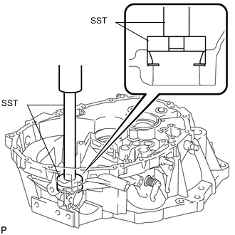
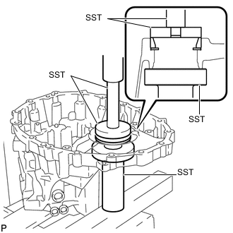
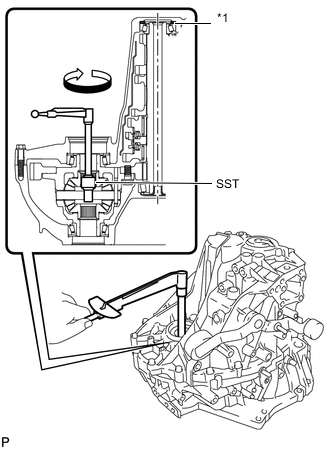
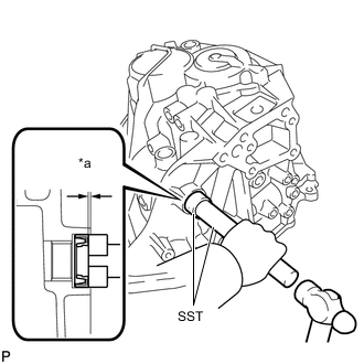
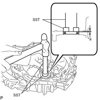
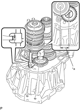
*1 Differential Case Assembly *a Urethane Insert SST until its urethane portion reaches portion A shown in the illustration.
- SST
- 09564-52020
-
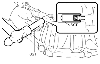
While holding portion B of SST, rotate portion C to expand the urethane portion of SST until it contacts the differential case assembly.
Tech Tips
If the urethane portion does not contact the differential case assembly, the rotation of SST and the differential case assembly will not be synchronized, making accurate preload measurement impossible.
-
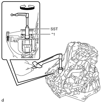
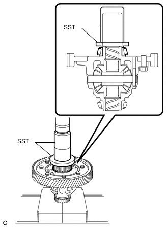
*1 Front Differential Case Rear Plate Washer Using SST and a torque wrench, turn the differential case assembly clockwise 2 or 3 times to allow the bearings to settle.
- SST
- 09564-52020
-
Using SST and a torque wrench, measure the preload.
- SST
- 09564-52020
Preload (at starting) New bearing 1.0 to 1.6 N*m (10 to 17 kgf*cm, 9 to 14 in.*lbf) Used bearing 0.8 to 1.3 N*m (9 to 13 kgf*cm, 8 to 12 in.*lbf) If the preload is out of specification, select a front differential case rear plate washer.
Front Differential Case Rear Plate Washer Thickness Part No. Mark Thickness
mm (in.)
90564-44039 10 2.100 (0.0827) 90564-44040 11 2.125 (0.0837) 90564-44041 12 2.150 (0.0846) 90564-44042 13 2.175 (0.0856) 90564-44043 14 2.200 (0.0866) 90564-44044 15 2.225 (0.0876) 90564-44045 16 2.250 (0.0886) 90564-44046 17 2.275 (0.0896) 90564-44047 18 2.300 (0.0906) 90564-44048 19 2.325 (0.0915) 90564-44049 20 2.350 (0.0925) 90564-44050 21 2.375 (0.0935) 90564-44051 22 2.400 (0.0945) 90564-44052 23 2.425 (0.0955) 90564-44053 24 2.450 (0.0965) 90564-44054 25 2.475 (0.0974) 90564-44055 26 2.500 (0.0984) 90564-44056 27 2.525 (0.0994) 90564-44057 28 2.550 (0.1004) 90564-44058 29 2.575 (0.1014) 90564-44059 30 2.600 (0.1024) 90564-44060 31 2.625 (0.1033) 90564-44061 32 2.650 (0.1043) 90564-44062 33 2.675 (0.1053) 90564-44063 34 2.700 (0.1063) 90564-44064 35 2.725 (0.1073) 90564-44065 36 2.750 (0.1083) 90564-44066 37 2.775 (0.1093) 90564-44067 38 2.800 (0.1102) 90564-44068 39 2.825 (0.1112) 90564-44069 40 2.850 (0.1122) Tech Tips
-
Select a thicker plate washer to increase the preload or a thinner plate washer to decrease the preload.
-
Make a memo as the torque values will be needed to adjust output shaft bearing preload.
-
Remove the 16 bolts and the manual transmission case from the front transaxle case.
-
Remove the differential case assembly from the front transaxle case.
-
-
INSTALL FRONT OUTPUT SHAFT BEARING
-
Install the output shaft cover to the front transaxle case.
Note
Insert the output shaft cover key into the front transaxle case groove.
-
Using SST and a press, install a new front output shaft bearing (outer race) to the front transaxle case.
- SST
- 09950-60011 ( 09951-00630 )
- 09950-70010 ( 09951-07100 )
-
-
INSTALL REAR OUTPUT SHAFT BEARING
-
Using SST and a press, install a new rear output shaft bearing (outer race) with the rear output shaft bearing shim to the manual transmission case.
- SST
- 09950-60011 ( 09951-00590 )
- 09950-70010 ( 09951-07200 )
Tech Tips
Use a rear output shaft bearing shim of the same thickness as the removed one.
-
-
ADJUST OUTPUT SHAFT BEARING PRELOAD (for 2NR-FKE)
-
Coat the differential case assembly with gear oil and install it to the front transaxle case.
-
Coat the output shaft assembly with gear oil and install it to the front transaxle case.
-
Install the manual transmission case to the front transaxle case with the 16 bolts.
- Torque:
- 29.4 N*m { 300 kgf*cm, 22 ft.*lbf }
-
*1 Rear Output Shaft Bearing Shim Using SST and a torque wrench, turn the differential case assembly clockwise and counterclockwise 2 or 3 times to allow the bearings to settle.
- SST
- 09564-32011
-
Using SST and a torque wrench, measure the preload. Calculate the rear output shaft bearing shim value using the following formula.
- SST
- 09564-32011
Formula Measured preload - Differential side bearing preload = Output shaft bearing preload Preload (at starting) New bearing 4.3 to 7.5 N*m (44 to 77 kgf*cm, 39 to 66 in.*lbf) Used bearing 2.8 to 4.8 N*m (29 to 49 kgf*cm, 25 to 43 in.*lbf) If the preload is out of specification, select a rear output shaft bearing shim.
Rear Output Shaft Bearing Shim Thickness Part No. Mark Thickness
mm (in.)
90564-45153 50 1.750 (0.0689) 90564-45154 51 1.775 (0.0699) 90564-45155 52 1.800 (0.0709) 90564-45156 53 1.825 (0.0719) 90564-45157 54 1.850 (0.0728) 90564-45158 55 1.875 (0.0738) 90564-45159 56 1.900 (0.0748) 90564-45160 57 1.925 (0.0758) 90564-45161 58 1.950 (0.0768) 90564-45162 59 1.975 (0.0778) 90564-45163 60 2.000 (0.0787) 90564-45164 61 2.025 (0.0797) 90564-45165 62 2.050 (0.0807) 90564-45166 63 2.075 (0.0817) 90564-45167 64 2.100 (0.0827) 90564-45168 65 2.125 (0.0837) 90564-45169 66 2.150 (0.0846) 90564-45170 67 2.175 (0.0856) 90564-45171 68 2.200 (0.0866) 90564-45172 69 2.225 (0.0876) 90564-45173 70 2.250 (0.0886) 90564-45174 71 2.275 (0.0896) 90564-45175 72 2.300 (0.0906) 90564-45176 73 2.325 (0.0915) 90564-45177 74 2.350 (0.0925) 90564-45178 75 2.375 (0.0935) 90564-45179 76 2.400 (0.0945) 90564-45180 77 2.425 (0.0955) 90564-45181 78 2.450 (0.0965) 90564-45182 79 2.475 (0.0974) 90564-45183 80 2.500 (0.0984) 90564-45184 81 2.525 (0.0994) 90564-45185 82 2.550 (0.1004) 90564-45186 83 2.575 (0.1014) 90564-45187 84 2.600 (0.1024) 90564-45188 85 2.625 (0.1033) 90564-45189 86 2.650 (0.1043) 90564-45190 87 2.675 (0.1053) 90564-45191 88 2.700 (0.1063) 90564-45192 89 2.725 (0.1073) 90564-45193 90 2.750 (0.1083) 90564-45194 91 2.775 (0.1093) 90564-45195 92 2.800 (0.1102) Tech Tips
Select a thicker shim to increase the preload or a thinner shim to decrease the preload.
-
Remove the 16 bolts and the manual transmission case from the front transaxle case.
-
Remove the output shaft assembly from the front transaxle case.
-
Remove the differential case assembly from the front transaxle case.
-
-
ADJUST OUTPUT SHAFT BEARING PRELOAD (for 2ZR-FE)
-
Coat the differential case assembly with gear oil and install it to the front transaxle case.
-
Coat the output shaft assembly with gear oil and install it to the front transaxle case.
-
Install the manual transmission case to the front transaxle case with the 16 bolts.
- Torque:
- 29.4 N*m { 300 kgf*cm, 22 ft.*lbf }
-
*1 Differential Case Assembly *a Urethane Insert SST until its urethane portion reaches portion A shown in the illustration.
- SST
- 09564-52020
-
While holding portion B of SST, rotate portion C to expand the urethane portion of SST until it contacts the differential case assembly.
Tech Tips
If the urethane portion does not contact the differential case assembly, the rotation of SST and the differential case assembly will not be synchronized, making accurate preload measurement impossible.
-
*1 Rear Output Shaft Bearing Shim Using SST and a torque wrench, turn the differential case assembly clockwise 2 or 3 times to allow the bearings to settle.
- SST
- 09564-52020
-
Using SST and a torque wrench, measure the preload. Calculate the rear output shaft bearing shim value using the following formula.
- SST
- 09564-52020
Formula Measured preload - Differential side bearing preload = Output shaft bearing preload Preload (at starting) New bearing 4.3 to 7.4 N*m (44 to 75 kgf*cm, 39 to 65 in.*lbf) Used bearing 2.8 to 4.7 N*m (29 to 47 kgf*cm, 25 to 41 in.*lbf) If the preload is out of specification, select a rear output shaft bearing shim.
Rear Output Shaft Bearing Shim Thickness Part No. Mark Thickness
mm (in.)
90564-45153 50 1.750 (0.0689) 90564-45154 51 1.775 (0.0699) 90564-45155 52 1.800 (0.0709) 90564-45156 53 1.825 (0.0719) 90564-45157 54 1.850 (0.0728) 90564-45158 55 1.875 (0.0738) 90564-45159 56 1.900 (0.0748) 90564-45160 57 1.925 (0.0758) 90564-45161 58 1.950 (0.0768) 90564-45162 59 1.975 (0.0778) 90564-45163 60 2.000 (0.0787) 90564-45164 61 2.025 (0.0797) 90564-45165 62 2.050 (0.0807) 90564-45166 63 2.075 (0.0817) 90564-45167 64 2.100 (0.0827) 90564-45168 65 2.125 (0.0837) 90564-45169 66 2.150 (0.0846) 90564-45170 67 2.175 (0.0856) 90564-45171 68 2.200 (0.0866) 90564-45172 69 2.225 (0.0876) 90564-45173 70 2.250 (0.0886) 90564-45174 71 2.275 (0.0896) 90564-45175 72 2.300 (0.0906) 90564-45176 73 2.325 (0.0915) 90564-45177 74 2.350 (0.0925) 90564-45178 75 2.375 (0.0935) 90564-45179 76 2.400 (0.0945) 90564-45180 77 2.425 (0.0955) 90564-45181 78 2.450 (0.0965) 90564-45182 79 2.475 (0.0974) 90564-45183 80 2.500 (0.0984) 90564-45184 81 2.525 (0.0994) 90564-45185 82 2.550 (0.1004) 90564-45186 83 2.575 (0.1014) 90564-45187 84 2.600 (0.1024) 90564-45188 85 2.625 (0.1033) 90564-45189 86 2.650 (0.1043) 90564-45190 87 2.675 (0.1053) 90564-45191 88 2.700 (0.1063) 90564-45192 89 2.725 (0.1073) 90564-45193 90 2.750 (0.1083) 90564-45194 91 2.775 (0.1093) 90564-45195 92 2.800 (0.1102) Tech Tips
Select a thicker shim to increase the preload or a thinner shim to decrease the preload.
-
Remove the 16 bolts and the manual transmission case from the front transaxle case.
-
Remove the output shaft assembly from the front transaxle case.
-
Remove the differential case assembly from the front transaxle case.
-
-
INSTALL OUTER SHIFT LEVER OIL SEAL
-
Text in Illustration *a Depth Using SST and a hammer, install a new outer shift lever oil seal to the manual transmission case.
- SST
- 09950-60011 ( 09951-00260 )
- 09950-70010 ( 09951-07100 )
Driven in depth 0.5 to 1.0 mm (0.0197 to 0.0393 in.) -
Coat the lip of the outer shift lever oil seal with MP grease.
-
-
INSTALL OUTER NO. 1 SHIFT LEVER
-
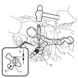
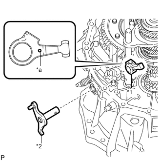
*1 Inner Shift Lever Slotted Spring Pin *2 Inner No. 1 Shift Lever *3 Outer No. 1 Shift Lever *a Depth *b Mark for 2NR-FKE:
-
Install the inner No. 1 shift lever, outer shift lever spacer and the outer No. 1 shift lever to the manual transmission case.
Driven in depth -0.5 to 0.5 mm (-0.0196 to 0.0196 in.) Tech Tips
Install the inner No. 1 shift lever with its mark facing outside of the manual transmission case.
-
-
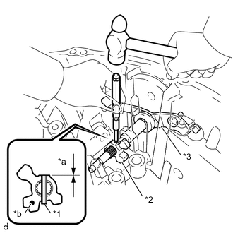
*1 Inner Shift Lever Slotted Spring Pin *2 Inner No. 1 Shift Lever *3 Outer No. 1 Shift Lever *a Depth *b Mark for 2ZR-FE:
-
Install the inner No. 1 shift lever, outer shift lever spacer and the outer No. 1 shift lever to the manual transmission case.
Driven in depth -0.5 to 0.5 mm (-0.0196 to 0.0196 in.) Tech Tips
Install the inner No. 1 shift lever with its mark facing outside of the manual transmission case.
-
-
Using a 5 mm pin punch and a hammer, install the inner shift lever slotted spring pin to the inner No. 1 shift lever.
-
-
INSTALL MANUAL TRANSMISSION OIL SEPARATOR SUB-ASSEMBLY
-
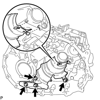
Install the manual transmission oil separator sub-assembly to the manual transmission case with the 4 bolts.
- Torque:
- 17 N*m { 173 kgf*cm, 13 ft.*lbf }
Tech Tips
Make sure that the end tabs of the manual transmission oil separator sub-assembly are inserted in the grooves of the manual transmission case.
-
-
INSTALL TRANSMISSION OIL SEPARATOR
-
Install the transmission oil separator to the manual transmission case with the 2 bolts.
- Torque:
- 17 N*m { 173 kgf*cm, 13 ft.*lbf }
Tech Tips
Make sure that the tip of the transmission oil separator is inserted in the groove of the manual transmission case.
-
-
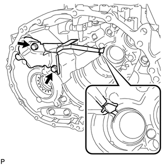
INSTALL NO. 1 OIL RECEIVER PIPE
-
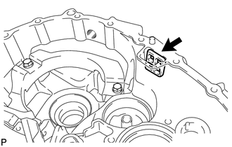
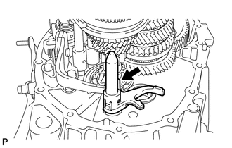
Install the No. 1 oil receiver pipe to the manual transmission case.
Tech Tips
Make sure that the No. 1 oil receiver pipe fully contacts the manual transmission case.
-
-
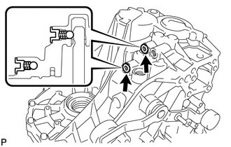
INSTALL STRAIGHT PIN
-
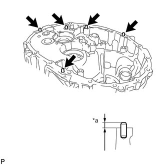
Text in Illustration *a Protrusion Height Using a plastic-faced hammer, tap in 5 new straight pins to the specified protrusion height.
Protrusion height 8.5 to 9.5 mm (0.335 to 0.374 in.)
-
-
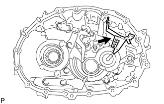
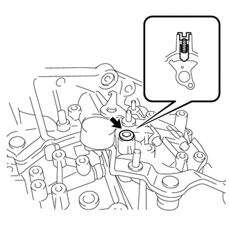
INSTALL REVERSE RESTRICT PIN ASSEMBLY
-
Install the reverse restrict pin assembly to the front transaxle case.
-
-
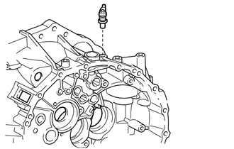
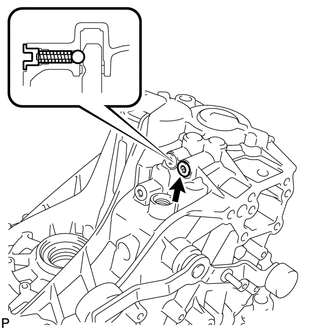
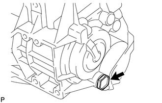
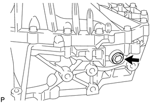
INSTALL BREATHER PLUG
-
Using SST and a hammer, install the breather plug to the front transaxle case.
- SST
- 09350-30020 ( 09350-07110 )
-
-
INSTALL TRANSMISSION OIL SEPARATOR
-
Install the transmission oil separator to the front transaxle case with the 4 bolts.
- Torque:
- 17 N*m { 173 kgf*cm, 13 ft.*lbf }
-
-
INSTALL FRONT TRANSAXLE CASE OIL SEAL
-
Text in Illustration *a Depth Using SST and a hammer, install a new front transaxle case oil seal to the front transaxle case.
- SST
- 09950-60011 ( 09951-00350 )
- 09950-70010 ( 09951-07100 )
Driven in depth 0.9 to 1.9 mm (0.0355 to 0.0748 in.) -
Coat the lip of the front transaxle case oil seal with MP grease.
-
-
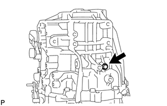
INSTALL TRANSMISSION MAGNET
-
Clean the transmission magnet and install it to the front transaxle case.
-
-
INSTALL INPUT SHAFT COVER
-
Install the input shaft cover to the manual transmission case.
Note
Insert the input shaft cover key into the manual transmission case groove.
-
-
INSTALL REAR INPUT SHAFT BEARING SHIM
-
Install the rear input shaft bearing shim to the manual transmission case.
Note
Apply MP grease to the shim as necessary to prevent the shim from falling off the case during assembly.
-
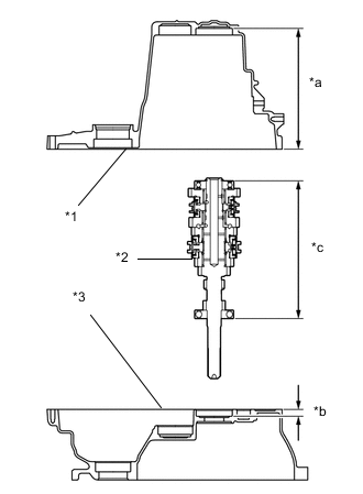
Text in Illustration *1 Manual Transmission Case *2 Input Shaft Assembly *3 Front Transaxle Case *a Dimension A *b Dimension B *c Dimension C Measure the area between the end of the manual transmission case and the rear input shaft bearing shim (Dimension A).
-
Measure the area between the end of the front transaxle case and the installation surface of the front input shaft bearing (Dimension B).
-
Measure the area between both input shaft bearing outer races (Dimension C).
Note
Measure Dimension C with each bearing having no axial clearance.
-
Calculate the rear input shaft bearing shim value using the following formula.
Formula (Dimension A + Dimension B) - Dimension C - rear input shaft bearing shim thickness = Between 0.02 mm (0.000788 in.) and 0.14 mm (0.00551 in.) If the thickness is out of specification, select a rear input shaft bearing shim.
Rear Input Shaft Bearing Shim Thickness Part No. Mark Thickness
mm (in.)
90564-54103 08 1.30 (0.0512) 90564-54104 09 1.35 (0.0531) 90564-54105 10 1.40 (0.0551) 90564-54106 11 1.45 (0.0571) 90564-54107 12 1.50 (0.0591) 90564-54108 13 1.55 (0.0610) 90564-54109 14 1.60 (0.0630) 90564-54110 15 1.65 (0.0650) 90564-54111 16 1.70 (0.0669) 90564-54112 17 1.75 (0.0689) 90564-54113 18 1.80 (0.0709) 90564-54114 19 1.85 (0.0728) -
Coat the rear input shaft bearing shim with MP grease and install it to the manual transmission case.
Note
Do not apply MP grease to the oil grooves.
-
-
INSTALL DIFFERENTIAL CASE ASSEMBLY
-
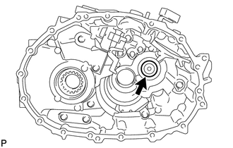
Coat the differential case tapered roller bearing with gear oil and install the differential case assembly to the front transaxle case.
-
-
INSTALL INPUT SHAFT ASSEMBLY
-
Apply gear oil to all sliding and rotating parts.
-
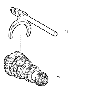
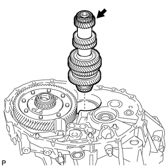
Text in Illustration *1 No. 1 Gear Shift Fork Shaft Assembly *2 Output Shaft Assembly Coat the No. 1 gear shift fork shaft assembly with gear oil and install it to the output shaft assembly.
-
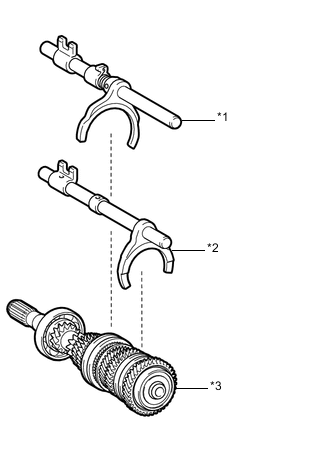
Text in Illustration *1 No. 2 Gear Shift Fork Shaft Assembly *2 No. 3 Gear Shift Fork Shaft Assembly *3 Input Shaft Assembly Coat the No. 2 gear shift fork shaft assembly and the No. 3 gear shift fork shaft assembly with gear oil and install them to the input shaft assembly.
-
Temporarily install the input shaft assembly, output shaft assembly and the 3 gear shift fork shaft assemblies, and tie them with a rope or string.
-
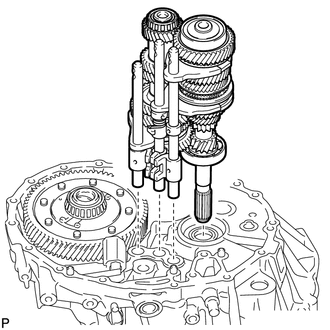
Install the input shaft assembly, output shaft assembly and the 3 gear shift fork shaft assemblies from the front transaxle case.
-
-
INSTALL OUTER SELECT LEVER OIL SEAL
-
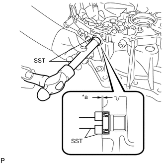
Text in Illustration *a Depth Using SST and a hammer, install a new outer select lever oil seal to the front transaxle case.
- SST
- 09950-60011 ( 09951-00240 )
- 09950-70010 ( 09951-07100 )
Driven in depth 0.5 to 1.0 mm (0.0197 to 0.0393 in.) -
Coat the lip of the outer select lever oil seal with MP grease.
-
-
INSTALL OUTER SELECT LEVER
-
Text in Illustration *1 Inner Select Lever *2 Outer Select Lever *a Mark Install the outer select lever and the inner select lever to the front transaxle case.
Tech Tips
Install the inner select lever with its mark positioned outside of the front transaxle case.
-
-
INSTALL SHIFT AND SELECT LEVER SHAFT ASSEMBLY
-
Text in Illustration *1 Shift and Select Lever Shaft Assembly *2 Shift Inter Lock Plate *3 Inner Select Lever Turn the shift and select lever shaft assembly and the shift inter lock plate counterclockwise and install them to the front transaxle case.
Tech Tips
When installing the inner select lever, make sure to engage it with the shift inter lock plate.
-
Coat the threads of the inner select lever set bolt with adhesive.
Adhesive Toyota Genuine Adhesive 1324, Three Bond 1324 or equivalent -
Using a 6 mm hexagon socket wrench, install the inner select lever set bolt.
- Torque:
- 28 N*m { 286 kgf*cm, 21 ft.*lbf }
-
-
INSTALL REVERSE SHIFT ARM BRACKET ASSEMBLY
-
Install the reverse shift arm bracket assembly to the front transaxle case with the 2 bolts.
- Torque:
- 17 N*m { 173 kgf*cm, 13 ft.*lbf }
-
-
INSTALL REVERSE SHIFT FORK SHAFT ASSEMBLY
-
Coat the reverse shift fork shaft assembly with gear oil and install it to the front transaxle case.
-
-
INSTALL REVERSE IDLER GEAR SUB-ASSEMBLY
-
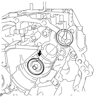
Text in Illustration *a Parallel Coat the reverse idler gear sub-assembly, reverse idler thrust washer and the reverse idler gear shaft with gear oil, and install them as shown in the illustration.
Note
Make sure that the reverse idler gear shaft bolt hole of the reverse idler gear shaft is parallel to the bolt hole on the front transaxle case.
Tech Tips
Raise the edge of the reverse shift arm bracket assembly and install it to the reverse shift fork shaft assembly.
-
-
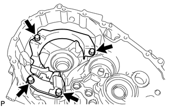
INSTALL MANUAL TRANSMISSION CASE
-
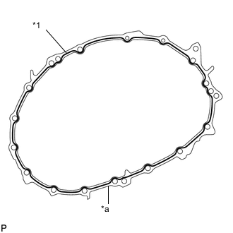
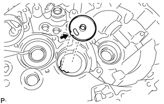
*1 Seal Packing *a Seal Diameter 1.2 mm (0.0472 in.) Apply seal packing to the manual transmission case as shown in the illustration.
Seal Packing Toyota Genuine Seal Packing 1281, Three Bond 1281 or equivalent Note
-
Remove any oil from the contact surfaces.
-
Assemble the parts within 10 minutes of application. Otherwise, the packing material must be removed and reapplied.
-
-
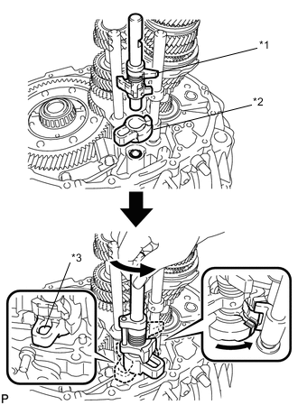
for 2NR-FKE:
-
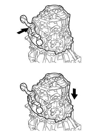
Push the outer No. 1 shift lever and install the manual transmission case to the front transaxle case.
Tech Tips
Pushing on the outer No. 1 shift lever allows the manual transmission case to be installed.
-
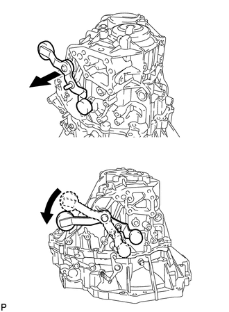
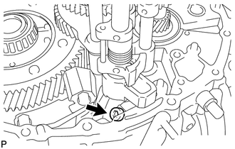
Pull the outer No. 1 shift lever out and turn it counterclockwise.
-
-
for 2ZR-FE:
-
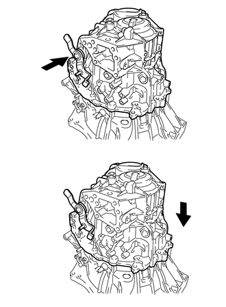
Push the outer No. 1 shift lever and install the manual transmission case to the front transaxle case.
Tech Tips
Pushing on the outer No. 1 shift lever allows the manual transmission case to be installed.
-
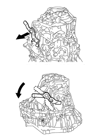
Pull the outer No. 1 shift lever out and turn it counterclockwise.
-
-
Install the 16 bolts.
- Torque:
- 29.4 N*m { 300 kgf*cm, 22 ft.*lbf }
-
-
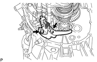
INSTALL OUTER SHIFT LEVER E RING
-
Install the outer shift lever E ring to the outer No. 1 shift lever.
-
-
INSTALL TRANSMISSION CASE OIL SEAL
-
INSTALL TRANSAXLE CASE OIL SEAL
-
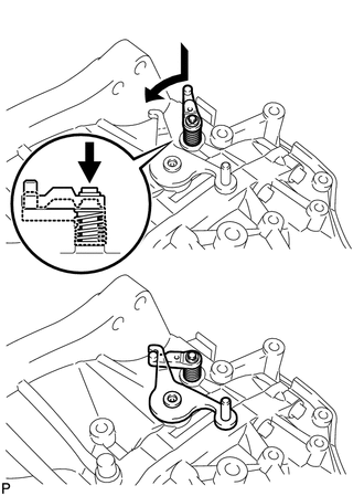
INSTALL SHIFT DETENT BALL
-
Install the 2 shift detent balls and the 2 shift detent ball compression springs to the manual transmission case.
-
Coat the threads of the 2 shift detent ball plugs with adhesive.
Adhesive Toyota Genuine Adhesive 1344, Three Bond 1344 or equivalent -
Using a 6 mm hexagon socket wrench, install the 2 shift detent ball plugs to the manual transmission case.
- Torque:
- 22 N*m { 224 kgf*cm, 16 ft.*lbf }
-
Install the shift detent ball and the shift detent ball compression spring to the manual transmission case.
-
Coat the threads of the shift detent ball plug with adhesive.
Adhesive Toyota Genuine Adhesive 1344, Three Bond 1344 or equivalent -
Using a 6 mm hexagon socket wrench, install the shift detent ball plug to the manual transmission case.
- Torque:
- 22 N*m { 224 kgf*cm, 16 ft.*lbf }
-
-
INSTALL LOCK BALL PIN
-
Install the lock ball pin and the shift and select lever shaft compression spring to the manual transmission case.
-
Coat the threads of the shift and select lever shaft straight screw with head plug with adhesive.
Adhesive Toyota Genuine Adhesive 1344, Three Bond 1344 or equivalent -
Using a 10 mm hexagon socket wrench, install the shift and select lever shaft straight screw with head plug to the manual transmission case.
- Torque:
- 24.5 N*m { 250 kgf*cm, 18 ft.*lbf }
-
-
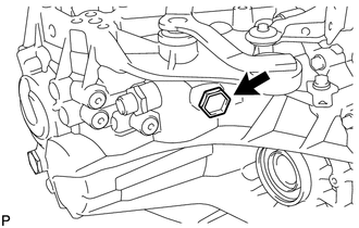
INSTALL REVERSE IDLER GEAR SHAFT BOLT
-
Coat the threads of the reverse idler gear shaft bolt with adhesive.
Adhesive Toyota Genuine Adhesive 1324, Three Bond 1324 or equivalent -
Install the reverse idler gear shaft bolt to the manual transmission case with a new gasket.
- Torque:
- 30 N*m { 306 kgf*cm, 22 ft.*lbf }
-
-
INSTALL NO. 1 LOCK BALL ASSEMBLY
-
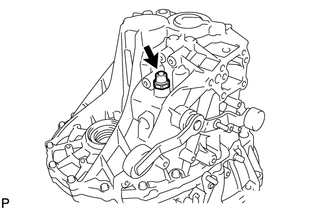
Coat the threads of the No. 1 lock ball assembly with adhesive.
Adhesive Toyota Genuine Adhesive 1344, Three Bond 1344 or equivalent -
Using a 24 mm deep socket wrench, install the No. 1 lock ball assembly to the manual transmission case.
- Torque:
- 29.4 N*m { 300 kgf*cm, 22 ft.*lbf }
-
-
INSTALL TRANSMISSION CASE PLUG
-
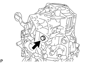
Install the transmission case plug to the manual transmission case with a new gasket.
- Torque:
- 28 N*m { 286 kgf*cm, 21 ft.*lbf }
-
-
INSTALL TRANSMISSION CASE PLUG (w/o Stop and Start System)
-
Install the transmission case plug to the manual transmission case with a new gasket.
- Torque:
- 40.2 N*m { 410 kgf*cm, 30 ft.*lbf }
-
-
INSTALL CLUTCH RELEASE CYLINDER WITH BEARING ASSEMBLY
-
INSTALL CLUTCH RELEASE BLEEDER SUB-ASSEMBLY
-
INSPECT CLUTCH PIPE LINE
-
INSTALL CLUTCH RELEASE BLEEDER SUB-ASSEMBLY
-
INSTALL NO. 1 CLUTCH HOUSING COVER
-
INSTALL CONTROL CABLE BRACKET ASSEMBLY
-
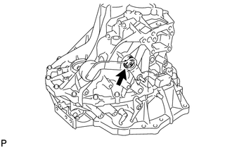
Hook the outer select lever to the low fixture lever of the reverse restrict pin assembly to secure it.
-
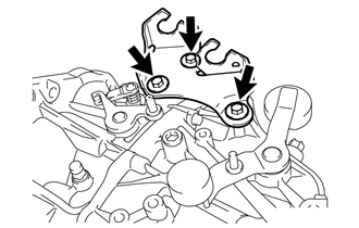
Install the control cable bracket assembly to the manual transmission case with the 3 bolts.
- Torque:
- 17 N*m { 173 kgf*cm, 13 ft.*lbf }
-
-
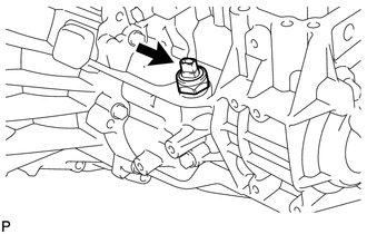
INSTALL PARK/NEUTRAL POSITION SWITCH ASSEMBLY (w/ Stop and Start System)
-
Using a 27 mm deep socket wrench, install the park/neutral position switch assembly to the manual transmission case with a new gasket.
- Torque:
- 40.2 N*m { 410 kgf*cm, 30 ft.*lbf }
-
-
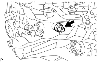
INSTALL BACK-UP LIGHT SWITCH ASSEMBLY
-
Using a 27 mm deep socket wrench, install the back-up light switch assembly to the manual transmission case with a new gasket.
- Torque:
- 40.2 N*m { 410 kgf*cm, 30 ft.*lbf }
-
-
INSTALL MANUAL TRANSMISSION FILLER PLUG
-
Install the manual transmission filler plug to the manual transmission case with a new gasket.
- Torque:
- 39.2 N*m { 400 kgf*cm, 29 ft.*lbf }
-
-
INSTALL MANUAL TRANSMISSION DRAIN PLUG
-
Using a 10 mm hexagon socket wrench, install the manual transmission drain plug to the front transaxle case with a new gasket.
- Torque:
- 45 N*m { 459 kgf*cm, 33 ft.*lbf }
-