MANUAL TRANSAXLE ASSEMBLY INSTALLATION
PROCEDURE
-
PRECAUTION
Note
When the transaxle is removed, be sure to use a new clutch release cylinder with bearing assembly and new installation bolts. Removal of the transaxle allows the compressed clutch release cylinder with bearing assembly to return to its original position, and dust from the moving section could damage the seal of the clutch release cylinder with bearing assembly, possibly causing clutch fluid leaks.
-
INSTALL CLUTCH RELEASE CYLINDER WITH BEARING ASSEMBLY
-
REMOVE CLUTCH RELEASE BLEEDER SUB-ASSEMBLY
-
INSPECT CLUTCH PIPE LINE
-
INSTALL CLUTCH RELEASE BLEEDER SUB-ASSEMBLY
-
INSTALL SPEEDOMETER DRIVEN HOLE COVER SUB-ASSEMBLY
-
Apply manual transaxle oil to a new O-ring and install it to the speedometer driven hole cover sub-assembly.
-
Install the speedometer driven hole cover sub-assembly to the manual transaxle assembly with the bolt.
- Torque:
- 11 N*m { 115 kgf*cm, 8 ft.*lbf }
-
-
INSTALL AIR TUBE SUPPORT
-
Install the air tube support to the manual transaxle assembly with the 2 bolts.
- Torque:
- 20 N*m { 199 kgf*cm, 14 ft.*lbf }
-
-
INSTALL MANUAL TRANSAXLE ASSEMBLY
-
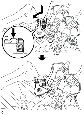
Text in Illustration *1 Reverse Restrict Pin Assembly *2 Outer Select Lever Hook the outer select lever of the manual transaxle assembly to the reverse restrict pin assembly to secure it.
-
Make sure that the knock pins are not loose, bent, damaged or scratched and then install the manual transaxle assembly to the engine assembly with the contact surfaces of the engine and transaxle flat against each other.
-
Using a transmission jack, align the input shaft with the clutch disc and install the manual transaxle assembly to the engine assembly.
-
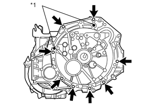
Text in Illustration *1 Knock Pin Hole Install the 8 bolts.
- Torque:
- for Flange Bolt
- 37 N*m { 377 kgf*cm, 27 ft.*lbf }
- for Bolt with Washer
- 33 N*m { 337 kgf*cm, 24 ft.*lbf }
Note
-
Be careful not to pinch wire harnesses, etc.
-
Do not allow the engine and transaxle to interfere with the vehicle body.
-
Do not forcefully pry on the transaxle.
-
To avoid damage to the input shaft, do not forcefully shake the transaxle.
-
Insert knock pins into the knock pin holes securely so that the end face of the transaxle fits close against the engine before tightening the bolts.
-
-
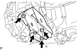
INSTALL ENGINE MOUNTING BRACKET SUB-ASSEMBLY LH
-
Clean and degrease the bolt and the bolt installation hole.
-
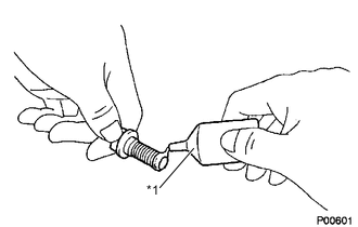
Text in Illustration *1 Adhesive Apply adhesive to 2 or 3 threads of the bolt end.
Adhesive Toyota Genuine Adhesive 1324, Three Bond 1324 or equivalent -
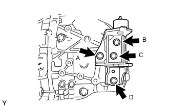
Install the engine mounting bracket sub-assembly LH with the 4 bolts in several steps.
- Torque:
- 64 N*m { 653 kgf*cm, 47 ft.*lbf }
Note
Temporarily tighten bolt A, and then fully tighten the 4 bolts in the order of B, C, D and A.
-
-
INSTALL ENGINE MOUNTING INSULATOR LH
-
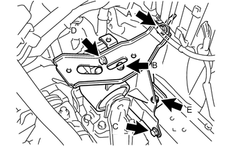
Install the engine mounting insulator LH with the 5 bolts in several steps.
- Torque:
- 52 N*m { 530 kgf*cm, 38 ft.*lbf }
Note
Temporarily tighten bolt A and B, and then fully tighten the 5 bolts in the order of C, D, E, A and B.
-
Install the engine mounting insulator LH to the engine mounting bracket sub-assembly LH with the bolt and nut.
- Torque:
- 52 N*m { 530 kgf*cm, 38 ft.*lbf }
Note
Turn the bolt while holding the nut.
-
-
INSTALL ENGINE MOVING CONTROL ROD BRACKET
-
Install the engine moving control rod bracket with the 4 bolts in several steps.
- Torque:
- 45 N*m { 459 kgf*cm, 33 ft.*lbf }
Note
Temporarily tighten bolt A, and then fully tighten the 4 bolts in the order of B, C, D and A.
-
-
INSTALL FRONT SUSPENSION CROSSMEMBER SUB-ASSEMBLY
-
INSTALL OIL PAN COVER
-
INSTALL EXHAUST PIPE
-
INSTALL FRONT DRIVE SHAFT ASSEMBLIES
-
INSTALL STARTER ASSEMBLY (except Cold Area Specification Vehicles)
-
INSTALL STARTER ASSEMBLY (for Cold Area Specification Vehicles)
-
INSTALL CLUTCH ACCUMULATOR ASSEMBLY
-
PLACE FRONT WHEELS FACING STRAIGHT AHEAD
-
INSTALL NO. 1 STEERING COLUMN HOLE COVER SUB-ASSEMBLY
-
INSTALL STEERING SLIDING YOKE SUB-ASSEMBLY
-
INSTALL COLUMN HOLE COVER SILENCER SHEET
-
CONNECT WIRE HARNESS
-
Engage the wire harness clamp and connect the back-up light switch connector.
-
Connect the wire harness to the manual transaxle assembly with the bolt.
- Torque:
- 13 N*m { 130 kgf*cm, 9 ft.*lbf }
-
-
CONNECT TRANSMISSION CONTROL CABLE ASSEMBLY
-
Install the 2 cables to the control cable bracket with the 2 new A clips.
-
Connect the 2 cables to the manual transaxle assembly with the 2 B clips.
-
-
ADJUST TRANSMISSION CONTROL SELECT CABLE
-
INSTALL NO. 1 AIR TUBE
-
INSTALL NO. 2 AIR HOSE
-
INSTALL BATTERY CARRIER (for LHD)
-
INSTALL BATTERY CARRIER (for RHD)
-
INSTALL BATTERY TRAY
-
INSTALL BATTERY
-
INSTALL AIR CLEANER BRACKET
-
INSTALL AIR CLEANER CASE SUB-ASSEMBLY
-
INSTALL AIR CLEANER FILTER ELEMENT SUB-ASSEMBLY
-
INSTALL AIR CLEANER CAP SUB-ASSEMBLY
-
INSTALL REAR CONSOLE BOX
-
ADD MANUAL TRANSAXLE OIL
-
CONNECT CABLE TO NEGATIVE BATTERY TERMINAL
- Torque:
- 5.4 N*m { 55 kgf*cm, 48 in.*lbf }
-
INSPECT SPEED SENSOR SIGNAL (w/o VSC)
-
INSPECT SPEED SENSOR SIGNAL (w/ VSC)
-
INSPECT AND ADJUST FRONT WHEEL ALIGNMENT
-
INSPECT MANUAL TRANSAXLE OIL LEVEL
-
INSPECT FOR MANUAL TRANSAXLE OIL LEAK
-
INSPECT FOR EXHAUST GAS LEAK
-
INSTALL ENGINE UNDER COVER LH
-
INSTALL ENGINE UNDER COVER RH
-
INSTALL CENTER ENGINE UNDER COVER