MANUAL TRANSAXLE ASSEMBLY REMOVAL
PROCEDURE
-
PRECAUTION
Note
-
When the transaxle is removed, be sure to use a new clutch release cylinder with bearing assembly and new installation bolts. Removal of the transaxle allows the compressed clutch release cylinder with bearing assembly to return to its original position, and dust from the moving section could damage the seal of the clutch release cylinder with bearing assembly, possibly causing clutch fluid leaks.
-
After turning the ignition switch off, waiting time may be required before disconnecting the cable from the battery terminal. Therefore, make sure to read the disconnecting the cable from the battery terminal notice before proceeding with work Click here.
-
-
DISCONNECT CABLE FROM NEGATIVE BATTERY TERMINAL
-
REMOVE REAR CONSOLE BOX
-
REMOVE BATTERY
-
REMOVE BATTERY TRAY
-
REMOVE BATTERY CARRIER
-
DISCONNECT WATER HOSE SUB-ASSEMBLY
-
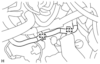
Disengage the 2 hose clamps and disconnect the water hose sub-assembly.
-
-
DISCONNECT WIRE HARNESS
-
Remove the bolt and disconnect the wire harness from transaxle assembly.
-
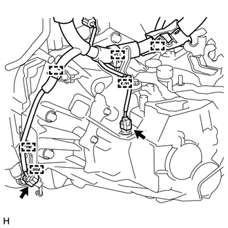
Disengage the 6 clamps and disconnect the 2 connectors.
-
-
DISCONNECT WIRE HARNESS (w/ Stop and Start System)
-
Disengage the 2 clamps and disconnect the park/neutral position switch connector.
-
-
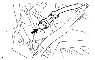
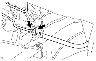
SEPARATE CLUTCH HOSE
-
Using a union nut wrench, separate the flexible hose tube from the clutch hose.
-
Remove the clip and separate the clutch hose from the flexible hose bracket.
-
-
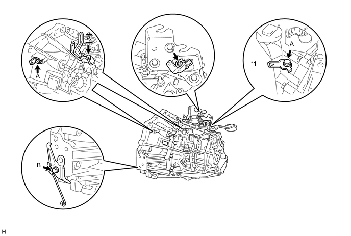
DISCONNECT TRANSMISSION CONTROL CABLE ASSEMBLY
-
REMOVE COLUMN HOLE COVER SILENCER SHEET (for LHD)
-
REMOVE COLUMN HOLE COVER SILENCER SHEET (for RHD)
-
REMOVE STEERING SLIDING YOKE SUB-ASSEMBLY (for LHD)
-
REMOVE STEERING SLIDING YOKE SUB-ASSEMBLY (for RHD)
-
REMOVE ENGINE UNDER COVER LH
-
REMOVE ENGINE UNDER COVER RH
-
DRAIN TRANSAXLE OIL
-
REMOVE FLYWHEEL HOUSING SIDE COVER (w/ Stop and Start System)
-
REMOVE STARTER ASSEMBLY (w/ Stop and Start System)
-
REMOVE FLYWHEEL HOUSING SIDE COVER (w/o Stop and Start System)
-
REMOVE STARTER ASSEMBLY (w/o Stop and Start System)
-
REMOVE FRONT DRIVE SHAFT ASSEMBLIES
-
REMOVE FRONT EXHAUST PIPE ASSEMBLY
-
SUSPEND ENGINE ASSEMBLY
-
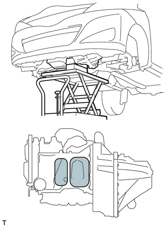
Support the engine assembly with an engine lifter so that it is stable shown in the illustration.
Text in Illustration 
Attachment Placement Positions
-
-
REMOVE FRONT SUSPENSION CROSSMEMBER SUB-ASSEMBLY
-
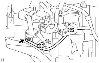
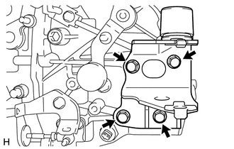
REMOVE ENGINE MOVING CONTROL ROD BRACKET
-
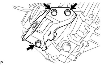
Remove the 3 bolts and the engine moving control rod bracket from the manual transaxle assembly.
-
-
SUPPORT MANUAL TRANSAXLE ASSEMBLY
-
Support the manual transaxle assembly with a transmission jack so that it is stable.
-
-
REMOVE ENGINE MOUNTING INSULATOR LH
-
Remove the bolt and nut and separate the engine mounting insulator LH from the engine mounting bracket sub-assembly LH.
Note
Turn the bolt while holding the nut.
-
Remove the 5 bolts and the engine mounting insulator LH.
-
-
REMOVE ENGINE MOUNTING BRACKET SUB-ASSEMBLY LH
-
Remove the 4 bolts and the engine mounting bracket sub-assembly LH from the manual transaxle assembly.
-
-
REMOVE MANUAL TRANSAXLE ASSEMBLY
-
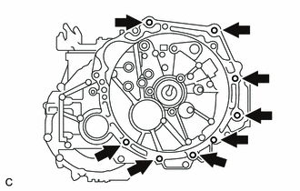
Remove the 8 bolts and the manual transaxle assembly.
Note
-
To avoid damage to the knock pins, do not pry between the transaxle and the engine.
-
To avoid damage to the input shaft, do not forcefully shake the transaxle.
-
-
-
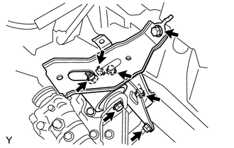
REMOVE WIRE HARNESS CLAMP BRACKET
Text in Illustration *1 Wire Harness Bracket (w/ Stop and Start System) - -
-
Remove the bolts and nut and wire harness clamp brackets as shown in the illustration.
-
-
REMOVE SPEEDOMETER DRIVEN HOLE COVER SUB-ASSEMBLY
-
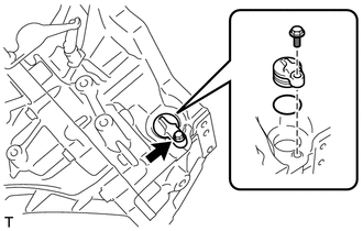
Remove the bolt and the speedometer driven hole cover sub-assembly from the manual transaxle assembly.
-
Remove the O-ring from the speedometer driven hole cover sub-assembly.
-
-
REMOVE CLUTCH RELEASE CYLINDER TO FLEXIBLE HOSE TUBE
-
REMOVE CLUTCH RELEASE BLEEDER SUB-ASSEMBLY
-
REMOVE CLUTCH TUBE BOOT
-
REMOVE CLUTCH RELEASE CYLINDER WITH BEARING ASSEMBLY
-
REMOVE CLUTCH RELEASE CYLINDER TO BLEEDER TUBE
-
REMOVE CLUTCH FLEXIBLE HOSE BRACKET