MANUAL TRANSAXLE ASSEMBLY(When Using the Engine Support Bridge for 2ZR-FE) INSTALLATION

PROCEDURE
-
PRECAUTION
Note
When the transaxle is removed, be sure to use a new clutch release cylinder with bearing assembly and new installation bolts. Removal of the transaxle allows the compressed clutch release cylinder with bearing assembly to return to its original position, and dust from the moving section could damage the seal of the clutch release cylinder with bearing assembly, possibly causing clutch fluid leaks.
-
INSTALL CLUTCH FLEXIBLE HOSE BRACKET
-
INSTALL CLUTCH RELEASE CYLINDER WITH BEARING ASSEMBLY
-
REMOVE CLUTCH RELEASE BLEEDER SUB-ASSEMBLY
-
INSPECT CLUTCH PIPE LINE
-
INSTALL CLUTCH RELEASE BLEEDER SUB-ASSEMBLY
-
INSTALL CLUTCH RELEASE CYLINDER TO FLEXIBLE HOSE TUBE
-
INSTALL SPEEDOMETER DRIVEN HOLE COVER SUB-ASSEMBLY
-
Apply manual transaxle oil to a new O-ring and install it to the speedometer driven hole cover sub-assembly.
-
Install the speedometer driven hole cover sub-assembly to the manual transaxle assembly with the bolt.
- Torque:
- 11.3 N*m { 115 kgf*cm, 8 ft.*lbf }
-
-
INSTALL WIRE HARNESS CLAMP BRACKET
-
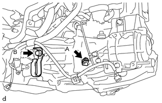
Install the wire harness clamp bracket and radiator hose clamp bracket to the manual transaxle assembly with the bolt B.
- Torque:
- 25.5 N*m { 260 kgf*cm, 19 ft.*lbf }
-
Install the wire harness clamp bracket to the manual transaxle assembly with the bolt A.
- Torque:
- 12.8 N*m { 131 kgf*cm, 9 ft.*lbf }
-
-
INSTALL MANUAL TRANSAXLE ASSEMBLY
-
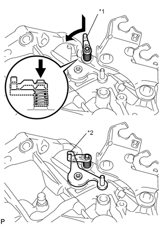
*1 Reverse Restrict Pin Assembly *2 Outer Select Lever Hook the outer lever to the low fixture lever of the reverse restrict pin to secure it.
-
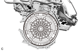
Confirm that the 2 knock pins are installed on the engine assembly and are not damaged.
-
Using a transmission jack, align the input shaft with the clutch disc and install the manual transaxle assembly to the engine assembly.
Note
-
Make sure that the wire harness or similar items are not pinched between the contact surfaces.
-
Do not forcibly pry on the manual transaxle assembly when installing it to the engine assembly.
-
Do not apply excessive force to the manual transaxle assembly as this will break the input shaft.
-
Make sure that the knock pins fit securely into the holes when installing the manual transaxle assembly to the engine assembly.
-
Make sure that the contact surfaces of the engine assembly and manual transaxle assembly are flat against each other before tightening the bolts.
-
-
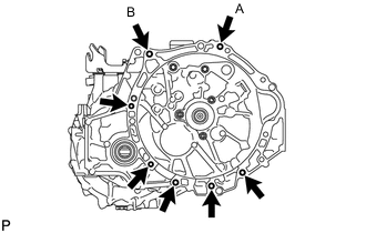
Temporarily install the bolt (A).
-
Install the bolt (B), then fully tighten the bolt (A).
- Torque:
- for Flange Bolt
- 37 N*m { 377 kgf*cm, 27 ft.*lbf }
- for Bolt with Washer
- 33 N*m { 337 kgf*cm, 24 ft.*lbf }
-
Install the 5 bolts.
- Torque:
- for Flange Bolt
- 37 N*m { 377 kgf*cm, 27 ft.*lbf }
- for Bolt with Washer
- 33 N*m { 337 kgf*cm, 24 ft.*lbf }
-
-
INSTALL ENGINE MOUNTING BRACKET SUB-ASSEMBLY LH
-
Clean and degrease the bolt and the bolt installation hole.
-
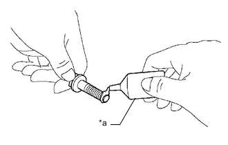
*a Adhesive Apply adhesive to 2 or 3 threads of the bolt end.
Adhesive Toyota Genuine Adhesive 1324, Three Bond 1324 or equivalent -
Install the engine mounting bracket sub-assembly LH with the 4 bolts.
- Torque:
- 64 N*m { 653 kgf*cm, 47 ft.*lbf }
-
-
INSTALL ENGINE MOUNTING INSULATOR LH
-
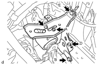
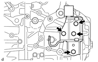
Install the engine mounting insulator LH with the 5 bolts in several steps.
- Torque:
- 52 N*m { 530 kgf*cm, 38 ft.*lbf }
Note
Temporarily tighten bolt A, and then fully tighten the 5 bolts in the order of B, C, D, E and A.
-
Install the engine mounting insulator LH to the engine mounting bracket sub-assembly LH with the bolt and nut.
- Torque:
- 52 N*m { 530 kgf*cm, 38 ft.*lbf }
Note
Turn the bolt while holding the nut.
-
-
INSTALL ENGINE MOVING CONTROL ROD BRACKET
-
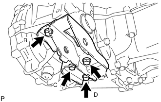
Install the engine moving control rod bracket with the 4 bolts in several steps.
- Torque:
- 45 N*m { 459 kgf*cm, 33 ft.*lbf }
Note
Temporarily tighten bolt A, and then fully tighten the 4 bolts in the order of B, C, D and A.
-
-
INSTALL FRONT SUSPENSION CROSSMEMBER SUB-ASSEMBLY
-
REMOVE ENGINE SUPPORT BRIDGE
-
Install the hood support rod.
-
Remove SST from the vehicle body.
Note
Prevent SST from contacting the vehicle body or windshield glass.
-
Remove the 2 nuts from the front suspension upper to cowl brace bracket.
-
Engage the 4 clamps to install the suction tube sub-assembly B and the liquid tube sub-assembly A.
-
Install the bolt.
- Torque:
- 9.8 N*m { 100 kgf*cm, 87 in.*lbf }
-
-
REMOVE ENGINE HANGER
-
INSTALL FRONT EXHAUST PIPE ASSEMBLY
-
INSTALL FRONT FLOOR CENTER BRACE
-
INSTALL FRONT DRIVE SHAFT ASSEMBLIES
-
INSTALL FLYWHEEL HOUSING SIDE COVER
-
INSTALL STARTER ASSEMBLY
-
CONNECT TRANSMISSION CONTROL CABLE ASSEMBLY
-
Install the 2 cables to the control cable bracket with 2 new clips.
-
Connect the 2 cables to the transaxle and install the 2 clips.
-
-
ADJUST TRANSMISSION CONTROL CABLE ASSEMBLY
-
INSTALL REAR CONSOLE BOX
-
INSTALL CLUTCH HOSE
-
Install the clutch hose to the flexible hose bracket with a new clip.
-
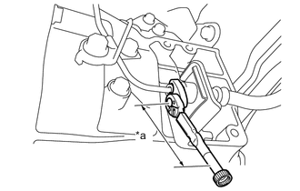
*a Torque Wrench Fulcrum Length Using a 10 mm union nut wrench, install the clutch release cylinder to flexible hose tube to the clutch hose.
- Torque:
- Specified Tightening Torque
- 15.2 N*m { 155 kgf*cm, 11 ft.*lbf }
Note
-
Do not kink or damage the clutch hose.
-
Do not allow any foreign matter such as dirt or dust to enter the clutch hose from the clip or bracket.
Tech Tips
-
Calculate the torque wrench reading when changing the fulcrum length of the torque wrench.
-
When using a union nut wrench (fulcrum length of 22 mm (0.866 in.)) + torque wrench (fulcrum length of 162 mm (6.38 in.)): 13.4 N*m (137 kgf*cm, 10 ft.*lbf)
-
-
CONNECT ENGINE WIRE
-
Engage the 2 clamps and connect the connector.
-
-
INSTALL NO. 3 ENGINE WIRE
-
Connect the No. 3 engine wire to the manual transaxle assembly with the bolt.
- Torque:
- 12.8 N*m { 131 kgf*cm, 9 ft.*lbf }
-
Engage the clamp.
-
-
INSTALL BATTERY CARRIER
-
INSTALL BATTERY TRAY
-
INSTALL BATTERY
-
INSTALL AIR CLEANER BRACKET
-
Install the air cleaner bracket with the 2 bolts.
- Torque:
- 19.5 N*m { 199 kgf*cm, 14 ft.*lbf }
-
Engage the clamp.
-
-
INSTALL AIR CLEANER CASE SUB-ASSEMBLY
-
INSTALL AIR CLEANER FILTER ELEMENT SUB-ASSEMBLY
-
INSTALL AIR CLEANER CAP WITH AIR CLEANER HOSE
-
CONNECT NO. 2 VENTILATION HOSE
-
INSTALL FRONT SUSPENSION UPPER CENTER BRACE SUB-ASSEMBLY
-
INSTALL OUTER COWL TOP PANEL (for LHD)
-
INSTALL OUTER COWL TOP PANEL (for RHD)
-
INSTALL INNER COWL TOP TO COWL BRACE (for LHD)
-
INSTALL INNER COWL TOP TO COWL BRACE (for RHD)
-
INSTALL FRONT NO. 1 VENTILATOR SEAL (for LHD)
-
INSTALL FRONT NO. 1 VENTILATOR SEAL (for RHD)
-
INSTALL FRONT AIR SHUTTER SEAL RH (for LHD)
-
INSTALL FRONT AIR SHUTTER SEAL RH (for RHD)
-
INSTALL WINDSHIELD WIPER MOTOR AND LINK
-
CONNECT CABLE TO NEGATIVE BATTERY TERMINAL
- Torque:
- 5.4 N*m { 55 kgf*cm, 48 in.*lbf }
Note
When disconnecting the cable, some systems need to be initialized after the cable is reconnected.
-
ADD TRANSAXLE OIL
-
CHECK FOR SPEED SENSOR SIGNAL
-
INSPECT AND ADJUST FRONT WHEEL ALIGNMENT
-
INSPECT FOR EXHAUST GAS LEAK
Tech Tips
Perform "Inspection After Repairs" after repairing or replacing the exhaust system.
-
INSPECT MANUAL TRANSAXLE OIL LEAK
-
INSTALL ENGINE UNDER COVER RH
-
INSTALL ENGINE UNDER COVER LH