MANUAL TRANSAXLE ASSEMBLY INSTALLATION
PROCEDURE
-
PRECAUTION
Note
When the transaxle is removed, be sure to use a new clutch release cylinder with bearing assembly and new installation bolts. Removal of the transaxle allows the compressed clutch release cylinder with bearing assembly to return to its original position, and dust from the moving section could damage the seal of the clutch release cylinder with bearing assembly, possibly causing clutch fluid leaks.
-
INSTALL CLUTCH FLEXIBLE HOSE BRACKET
-
INSTALL CLUTCH RELEASE CYLINDER WITH BEARING ASSEMBLY
-
REMOVE CLUTCH RELEASE BLEEDER SUB-ASSEMBLY
-
INSPECT CLUTCH PIPE LINE
-
INSTALL CLUTCH RELEASE BLEEDER SUB-ASSEMBLY
-
INSTALL SPEEDOMETER DRIVEN HOLE COVER SUB-ASSEMBLY
-
Apply manual transaxle oil to a new O-ring and install it to the speedometer driven hole cover sub-assembly.
-
Install the speedometer driven hole cover sub-assembly to the manual transaxle assembly with the bolt.
- Torque:
- 11 N*m { 115 kgf*cm, 8 ft.*lbf }
-
-
INSTALL CLUTCH RELEASE CYLINDER TO FLEXIBLE HOSE TUBE
-
INSTALL WIRE HARNESS CLAMP BRACKET (w/ Stop and Start System)
-
Install the 5 wire harness clamp brackets with the 5 bolts as shown in the illustration.
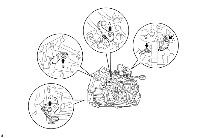
- Torque:
- Bolt A
- 13 N*m { 130 kgf*cm, 9 ft.*lbf }
- Bolt B
- 20 N*m { 204 kgf*cm, 15 ft.*lbf }
- Bolt C
- 63 N*m { 642 kgf*cm, 46 ft.*lbf }
-
-
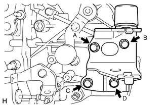
INSTALL WIRE HARNESS CLAMP BRACKET (w/o Stop and Start System)
-
Install the 3 wire harness clamp brackets with the 3 bolts as shown in the illustration.
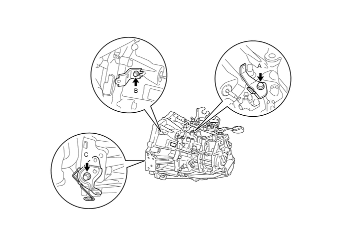
- Torque:
- Bolt A
- 13 N*m { 130 kgf*cm, 9 ft.*lbf }
- Bolt B
- 20 N*m { 204 kgf*cm, 15 ft.*lbf }
- Bolt C
- 63 N*m { 642 kgf*cm, 46 ft.*lbf }
-
-
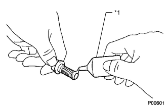
INSTALL MANUAL TRANSAXLE ASSEMBLY
-
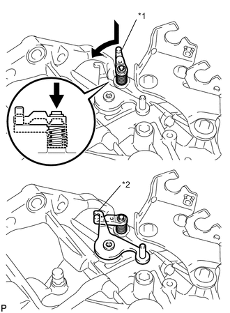
Text in Illustration *1 Reverse Restrict Pin Assembly *2 Outer Select Lever Hook the outer lever to the low fixture lever of the reverse restrict pin to secure it.
-
Make sure that the knock pins are not loose, bent, damaged or scratched and then install the transaxle onto the engine with the contact surfaces of the engine and transaxle flat against each other.
-
Using a transmission jack, align the input shaft with the clutch disc and install the manual transaxle assembly to the engine assembly.
-
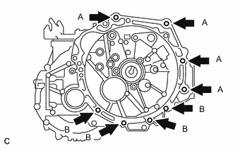
Install the 8 bolts.
- Torque:
- Bolt A
- 64 N*m { 653 kgf*cm, 47 ft.*lbf }
- Bolt B
- 39 N*m { 397 kgf*cm, 29 ft.*lbf }
Note
-
Be careful not to pinch wire harnesses, etc.
-
To avoid damage to the input shaft, do not forcefully shake the transaxle.
-
Insert knock pins into the knock pin holes securely so that the end face of the transaxle fits close against the engine before tightening the bolts.
-
-
INSTALL ENGINE MOUNTING BRACKET SUB-ASSEMBLY LH
-
Clean and degrease the bolt and the bolt installation hole.
-
Text in Illustration *1 Toyota Genuine Adhesive 1324 Apply adhesive to 2 or 3 threads of the bolt end.
Adhesive Toyota Genuine Adhesive 1324, Three Bond 1324 or equivalent -
Install the engine mounting bracket sub-assembly LH with the 4 bolts in several steps.
- Torque:
- 64 N*m { 653 kgf*cm, 47 ft.*lbf }
Note
Temporarily tighten bolt A, and then fully tighten the 4 bolts in the order of B, D, C and A.
-
-
INSTALL ENGINE MOUNTING INSULATOR LH
-
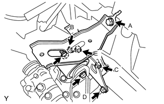
Install the engine mounting insulator LH with the 5 bolts in several steps.
- Torque:
- 52 N*m { 530 kgf*cm, 38 ft.*lbf }
Note
Temporarily tighten bolt A and B, and then fully tighten the 5 bolts in the order of C, D, E, A and B.
-
Install the engine mounting insulator LH to the engine mounting bracket sub-assembly LH with the bolt and nut.
- Torque:
- 52 N*m { 530 kgf*cm, 38 ft.*lbf }
Note
Turn the bolt while holding the nut.
-
-
INSTALL ENGINE MOVING CONTROL ROD BRACKET
-
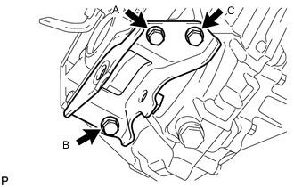
Install the engine moving control rod bracket with the 3 bolts in several steps.
- Torque:
- 45 N*m { 459 kgf*cm, 33 ft.*lbf }
Note
Temporarily tighten bolt A, and then fully tighten the 3 bolts in the order of B, C and A.
-
-
INSTALL FRONT SUSPENSION CROSSMEMBER SUB-ASSEMBLY
-
INSTALL FRONT EXHAUST PIPE ASSEMBLY
-
INSTALL FRONT DRIVE SHAFT ASSEMBLIES
-
INSTALL STARTER ASSEMBLY (w/ Stop and Start System)
-
INSTALL FLYWHEEL HOUSING SIDE COVER (w/ Stop and Start System)
-
INSTALL STARTER ASSEMBLY (w/o Stop and Start System)
-
INSTALL FLYWHEEL HOUSING SIDE COVER (w/o Stop and Start System)
-
CONNECT TRANSMISSION CONTROL CABLE ASSEMBLY
-
Install the 2 cables to the control cable bracket with 2 new clips.
-
Connect the 2 cables to the transaxle and install the 2 washers and the 2 clips.
-
-
ADJUST TRANSMISSION CONTROL CABLE ASSEMBLY
-
INSTALL REAR CONSOLE BOX
-
INSTALL CLUTCH HOSE
-
Install the clutch hose to the flexible hose bracket with a new clip.
-
Using a union nut wrench 10 mm, install the flexible hose tube to the clutch hose.
- Torque:
- 15 N*m { 155 kgf*cm, 11 ft.*lbf }
Note
Use the formula to calculate special torque values for situations where a union nut wrench is combined with a torque wrench.
-
-
CONNECT WIRE HARNESS (w/ Stop and Start System)
-
Engage the 2 clamps and connect the neutral position switch connector.
-
-
CONNECT WIRE HARNESS
-
Engage the 6 clamps and connect the 3 connectors.
-
Connect the wire harness to the transaxle assembly with the bolt.
- Torque:
- 13 N*m { 130 kgf*cm, 9 ft.*lbf }
-
-
INSTALL BATTERY CARRIER
-
INSTALL BATTERY TRAY
-
INSTALL BATTERY
-
ADD TRANSAXLE OIL
-
INSPECT MANUAL TRANSAXLE OIL LEVEL
-
INSTALL ENGINE UNDER COVER RH
-
INSTALL ENGINE UNDER COVER LH
-
INSTALL STEERING SLIDING YOKE SUB-ASSEMBLY (for LHD)
-
INSTALL STEERING SLIDING YOKE SUB-ASSEMBLY (for RHD)
-
INSTALL COLUMN HOLE COVER SILENCER SHEET (for LHD)
-
INSTALL COLUMN HOLE COVER SILENCER SHEET (for RHD)
-
CONNECT CABLE TO NEGATIVE BATTERY TERMINAL
- Torque:
- 5.4 N*m { 55 kgf*cm, 48 in.*lbf }
Note
When disconnecting the cable, some systems need to be initialized after the cable is reconnected.
-
INSPECT ABS SPEED SENSOR SIGNAL (w/o VSC)
-
INSPECT ABS SPEED SENSOR SIGNAL (w/ VSC)
-
INSPECT AND ADJUST FRONT WHEEL ALIGNMENT
-
INSPECT FOR EXHAUST GAS LEAK
Tech Tips
Perform "Inspection After Repairs" after repairing or replacing the exhaust system.
-
INSPECT MANUAL TRANSAXLE OIL LEAK