MANUAL TRANSAXLE ASSEMBLY(When Not Using the Engine Support Bridge for 2ZR-FE) INSTALLATION
CAUTION / NOTICE / HINT
CAUTION:
The engine assembly with transaxle is very heavy. Be sure to follow the procedure described in the repair manual, or the engine lifter may suddenly drop.
Note
When the manual transaxle assembly is removed, be sure to use a new clutch release cylinder with bearing assembly and new installation bolts. Removal of the transaxle allows the compressed clutch release cylinder with bearing assembly to return to its original position. Dust from the moving section may damage the seal of the clutch release cylinder with bearing assembly, possibly causing clutch fluid leaks.
PROCEDURE
-
INSTALL CLUTCH FLEXIBLE HOSE BRACKET
-
INSTALL CLUTCH RELEASE CYLINDER WITH BEARING ASSEMBLY
-
REMOVE CLUTCH RELEASE BLEEDER SUB-ASSEMBLY
-
INSPECT CLUTCH PIPE LINE
-
INSTALL CLUTCH RELEASE BLEEDER SUB-ASSEMBLY
-
INSTALL CLUTCH RELEASE CYLINDER TO FLEXIBLE HOSE TUBE
-
INSTALL SPEEDOMETER DRIVEN HOLE COVER SUB-ASSEMBLY
-
INSTALL WIRE HARNESS CLAMP BRACKET
-
INSTALL ENGINE MOUNTING BRACKET SUB-ASSEMBLY LH
-
INSTALL MANUAL TRANSAXLE ASSEMBLY
-
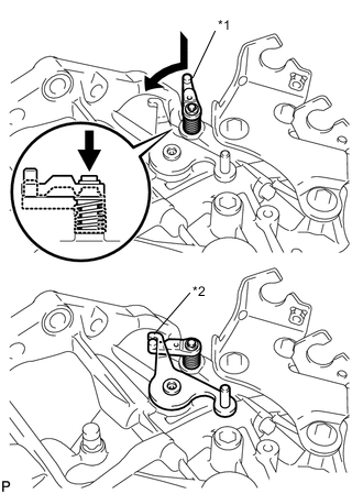
*1 Reverse Restrict Pin Assembly *2 Outer Select Lever Hook the outer lever to the low fixture lever of the reverse restrict pin to secure it.
-
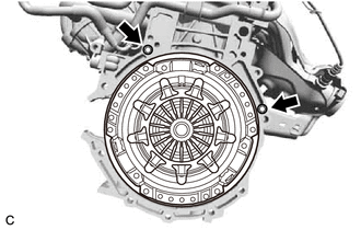
Confirm that the 2 knock pins are installed on the engine assembly and are not damaged.
-
Align the input shaft with the clutch disc and install the manual transaxle assembly to the engine assembly.
Note
-
Make sure that the wire harness or similar items are not pinched between the contact surfaces.
-
Do not forcibly pry on the manual transaxle assembly when installing it to the engine assembly.
-
Do not apply excessive force to the manual transaxle assembly as this will break the input shaft.
-
Make sure that the knock pins fit securely into the holes when installing the manual transaxle assembly to the engine assembly.
-
Make sure that the contact surfaces of the engine assembly and manual transaxle assembly are flat against each other before tightening the bolts.
-
-
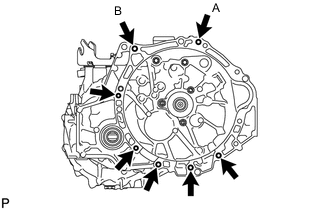
Temporarily install the bolt (A).
-
Install the bolt (B), then fully tighten the bolt (A).
- Torque:
- for Flange Bolt
- 37 N*m { 377 kgf*cm, 27 ft.*lbf }
- for Bolt with Washer
- 33 N*m { 337 kgf*cm, 24 ft.*lbf }
-
Install the 5 bolts.
- Torque:
- for Flange Bolt
- 37 N*m { 377 kgf*cm, 27 ft.*lbf }
- for Bolt with Washer
- 33 N*m { 337 kgf*cm, 24 ft.*lbf }
-
-
INSTALL ENGINE MOVING CONTROL ROD BRACKET
-
INSTALL FRONT SUSPENSION CROSSMEMBER SUB-ASSEMBLY
-
Install the front suspension crossmember sub-assembly to the engine moving control rod with the bolt.
- Torque:
- 120 N*m { 1224 kgf*cm, 89 ft.*lbf }
-
-
CONNECT ENGINE WIRE
-
INSTALL NO. 3 ENGINE WIRE
-
INSTALL FLYWHEEL HOUSING SIDE COVER
-
INSTALL STARTER ASSEMBLY
-
INSTALL ENGINE ASSEMBLY WITH TRANSAXLE