OUTPUT SHAFT INSPECTION

PROCEDURE
-
INSPECT 1ST GEAR THRUST CLEARANCE
-
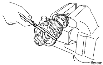
Using a feeler gauge, measure the 1st gear thrust clearance.
Standard clearance 0.10 to 0.45 mm (0.0039 to 0.0177 in.) Maximum clearance 0.45 mm (0.0177 in.) If the clearance is more than the maximum, replace the No. 1 transmission clutch hub, 1st gear or output shaft. Replace the part or parts determined to be the most likely cause of the problem.
-
-
INSPECT 2ND GEAR THRUST CLEARANCE
-
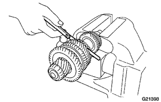
Using a feeler gauge, measure the 2nd gear thrust clearance.
Standard clearance 0.10 to 0.55 mm (0.0039 to 0.0217 in.) Maximum clearance 0.55 mm (0.0217 in.) If the clearance is more than the maximum, replace the 2nd gear, No. 1 transmission clutch hub, 3rd driven gear or output shaft. Replace the part or parts determined to be the most likely cause of the problem.
-
-
INSPECT 1ST GEAR RADIAL CLEARANCE
-
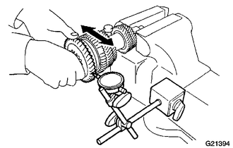
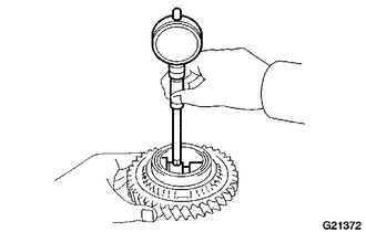
Using a dial indicator, measure the 1st gear radial clearance.
Standard clearance 0.015 to 0.056 mm (0.0006 to 0.0022 in.) Maximum clearance 0.056 mm (0.0022 in.) If the clearance is more than the maximum, replace the 1st gear needle roller bearing, 1st gear or output shaft. Replace the part or parts determined to be the most likely cause of the problem.
-
-
INSPECT 2ND GEAR RADIAL CLEARANCE
-
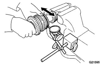
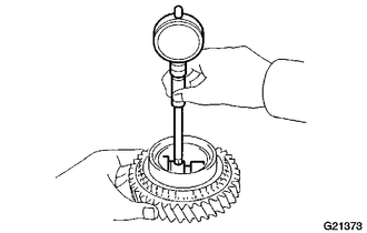
Using a dial indicator, measure the 2nd gear radial clearance.
Standard clearance 0.015 to 0.056 mm (0.0006 to 0.0022 in.) Maximum clearance 0.056 mm (0.0022 in.) If the clearance is more than the maximum, replace the 2nd gear needle roller bearing, 2nd gear or output shaft. Replace the part or parts determined to be the most likely cause of the problem.
-
-
INSPECT OUTPUT SHAFT
-
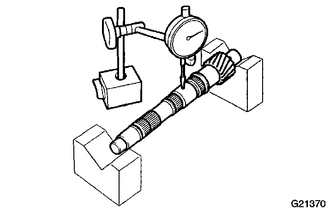
Using a dial indicator, check the shaft runout.
Maximum runout 0.03 mm (0.0012 in.) If the runout is more than the maximum, replace the output shaft.
-
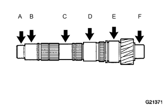
Using a micrometer, measure the outer diameter of the output shaft journals at the locations indicated in the illustration.
Standard outer diameter Part A 23.002 to 23.015 mm (0.9056 to 0.9061 in.) Part B and C 28.3 mm (1.1142 in.) Part D and E 33.985 to 34.000 mm (1.3380 to 1.3386 in.) Part F 25.002 to 25.015 mm (0.9843 to 0.9848 in.) If the outer diameter is less than the minimum, replace the output shaft.
-
-
INSPECT 1ST GEAR
-
Using a cylinder gauge, measure the inside diameter of the 1st gear.
Standard inside diameter 39.015 to 39.031 mm (1.5360 to 1.5367 in.) Maximum inside diameter 39.031 mm (1.5367 in.) If the inside diameter is more than the maximum, replace the 1st gear.
-
-
INSPECT 2ND GEAR
-
Using a cylinder gauge, measure the inside diameter of the 2nd gear.
Standard inside diameter 39.015 to 39.031 mm (1.5360 to 1.5367 in.) Maximum inside diameter 39.031 mm (1.5367 in.) If the inside diameter is more than the maximum, replace the 2nd gear.
-
-
INSPECT 1ST GEAR SYNCHRONIZER RING
-
Check for wear and damage.
-
Coat the 1st gear cone with gear oil.
-
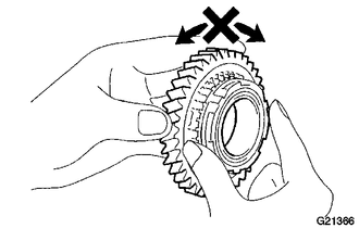
Turn the synchronizer ring in both directions while pushing it against the 1st gear cone and check that it locks in both directions. If the 1st gear synchronizer ring does not lock, replace the 1st gear synchronizer ring.
-
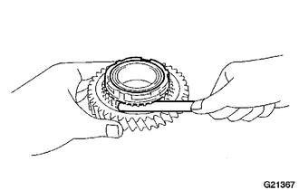
Using a feeler gauge, measure the clearance between the 1st gear synchronizer ring back and the gear spline end.
Standard clearance 0.8 to 1.6 mm (0.031 to 0.063 in.) Minimum clearance 0.8 mm (0.031 in.) If the clearance is less than the minimum, replace the 1st gear synchronizer ring.
-
-
INSPECT 2ND GEAR SYNCHRONIZER RING
-
Check for wear and damage.
-
Coat the 2nd gear cone with gear oil.
-
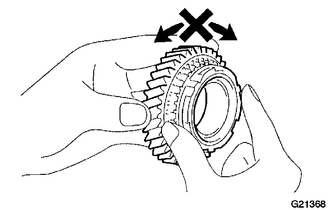
Turn the 2nd gear synchronizer ring in both directions while pushing it against the 2nd gear cone and check that it locks in both directions. If the 2nd gear synchronizer ring does not lock, replace the 2nd gear synchronizer ring.
-
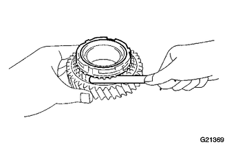
Using a feeler gauge, measure the clearance between the 2nd gear synchronizer ring back and the gear spline end.
Standard clearance 0.8 to 1.6 mm (0.031 to 0.063 in.) Minimum clearance 0.8 mm (0.031 in.) If the clearance is less than the minimum, replace the 2nd gear synchronizer ring.
-
-
INSPECT REVERSE GEAR
-
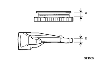
Using a vernier caliper, measure the width of the reverse gear groove (A) and the thickness of the claw part on the No. 1 gear fork (B), and then calculate the clearance.
Standard clearance (A-B) 0.15 to 0.35 mm (0.0059 to 0.0138 in.) If the clearance is not as specified, replace the No. 1 gear shift fork and reverse gear.
-