MANUAL TRANSAXLE UNIT REASSEMBLY

PROCEDURE
-
INSTALL OUTPUT SHAFT COVER
-
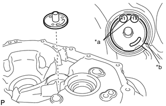
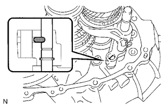
Text in Illustration *a Protrusion *b Oil Groove Install the output shaft cover to the front transaxle case as shown in the illustration.
-
-
INSTALL OUTPUT SHAFT FRONT BEARING
-
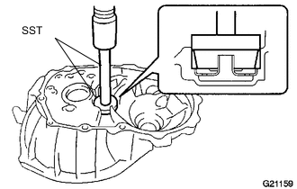
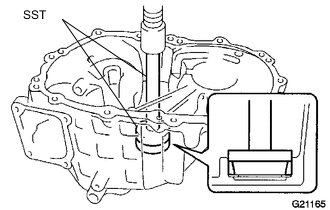
Using SST and a press, press in the output shaft front bearing outer race to the front transaxle case.
- SST
- 09950-60010 ( 09951-00510 )
- 09950-70010 ( 09951-07150 )
-
-
INSTALL FRONT DIFFERENTIAL CASE FRONT TAPERED ROLLER BEARING
-
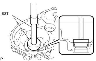
Using SST and a press, press in the front differential case front tapered roller bearing outer race to the front transaxle case.
- SST
- 09350-32014 ( 09351-32111, 09351-32130 )
-
-
INSTALL FRONT DIFFERENTIAL CASE REAR TAPERED ROLLER BEARING
-
Install the differential case shim to the manual transmission case.
Tech Tips
When reusing the front differential case rear tapered roller bearing, reuse the original shim. When installing a new front differential case rear tapered roller bearing, first select and install a shim which is thinner than the original.
-
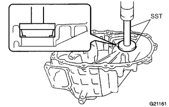
Using SST and a press, press in the front differential case rear tapered roller bearing outer race.
- SST
- 09950-60010 ( 09951-00620 )
- 09950-70010 ( 09951-07100 )
-
-
ADJUST DIFFERENTIAL SIDE BEARING PRELOAD
-
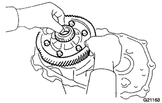
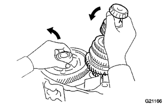
Coat the differential case with gear oil, and install it to the front transaxle case.
-
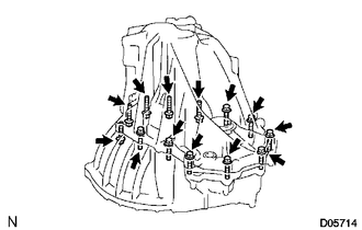
Install the manual transmission case with the 13 bolts.
- Torque:
- 29 N*m { 300 kgf*cm, 22 ft.*lbf }
Tech Tips
From manual transmission case side: 8 bolts From front transaxle case side: 5 bolts
-
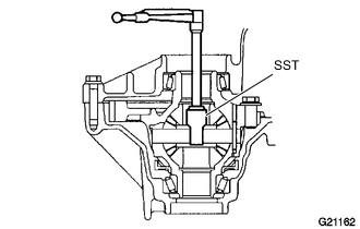
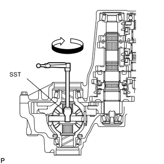
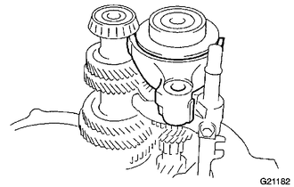
Using SST and a torque wrench, turn the differential case right and left 2 or 3 times to allow the bearings to settle.
- SST
- 09564-32011
-
Using SST and a torque wrench, measure the starting preload.
- SST
- 09564-32011
New bearing preload 0.78 to 1.57 N*m (7.96 to 16.00 kgf*cm, 6.9 to 13.89 in.*lbf) Used bearing preload 0.49 to 0.98 N*m (5.00 to 1.00 kgf*cm, 4.33 to 8.67 in.*lbf) If the preload is not as specified, replace the differential case shim with one of a different thickness. Use the table below to select a differential case shim which will ensure that the preload is within the specification.
Plate Shim Thickness Part No. Mark Thickness
mm (in.)
90564-41065 01 1.100 (0.0433) 90564-41066 02 1.150 (0.0453) 90564-41067 03 1.200 (0.0472) 90564-41068 04 1.250 (0.0492) 90564-41069 05 1.300 (0.0512) 90564-41070 06 1.350 (0.0532) 90564-41071 07 1.400 (0.0551) 90564-41072 08 1.450 (0.0571) 90564-41073 09 1.500 (0.0590) 90564-41074 10 1.550 (0.0610) 90564-41075 11 1.600 (0.0630) 90564-41076 12 1.650 (0.0650) 90564-41077 13 1.700 (0.0669) 90564-41078 14 1.750 (0.0689) 90564-41079 15 1.800 (0.0709) 90564-41080 16 1.850 (0.0728) 90564-41081 17 1.900 (0.0748) 90564-41082 18 1.950 (0.0768) 90564-41083 19 2.000 (0.0787) 90564-41014 AA 2.100 (0.0827) 90564-41015 BB 2.150 (0.0847) 90564-41016 CC 2.200 (0.0866) 90564-41017 DD 2.250 (0.0886) 90564-41018 EE 2.200 (0.0866) 90564-41019 FF 2.300 (0.0906) 90564-41020 GG 2.400 (0.0945) 90564-41021 HH 2.450 (0.0965) 90564-41022 JJ 2.500 (0.0984) 90564-41023 KK 2.550 (0.0915) 90564-41024 LL 2.600 (0.1004) 90564-41025 MM 2650 (0.1043) 90564-41026 NN 2.700 (0.1063) 90564-41027 PP 2.750 (0.1083) 90564-41028 QQ 2.800 (0.1102) 90564-41029 RR 2.850 (0.1122) 90564-41030 SS 2.900 (0.1142) 90564-41031 TT 2.950 (0.1161) 90564-41032 UU 3.000 (0.1181) Tech Tips
-
Select a thicker plate shim to increase the preload, or a thinner plate shim to decrease the preload.
-
Make a memo, as the torque values will be needed for the Adjust Output Shaft Bearing Preload procedure.
-
Remove the 13 bolts and the manual transmission case from the front transaxle case.
-
Remove the differential case assembly from the front transaxle case.
-
-
INSTALL REAR OUTPUT SHAFT BEARING
-
Install the rear output shaft bearing shim to the manual transmission case.
Tech Tips
When reusing the rear output shaft tapered roller bearing, reuse the original shim. When installing a new rear output shaft tapered roller bearing, first select and install a shim which is thinner than the original.
-
Using SST and a press, press in the rear output shaft bearing outer race to the manual transmission case.
- SST
- 09950-60010 ( 09951-00570 )
- 09950-70010 ( 09951-07200 )
-
-
ADJUST OUTPUT SHAFT BEARING PRELOAD
-
Install the output shaft assembly and the differential case to the front transaxle case.
-
Install the manual transmission case to the front transaxle case with the 13 bolts.
- Torque:
- 29 N*m { 300 kgf*cm, 22 ft.*lbf }
Tech Tips
Manual transmission case side: 8 bolts
Front transaxle case side: 5 bolts
-
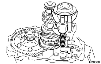
Using SST and a torque wrench, turn the differential case assembly and output shaft assembly clockwise and counterclockwise 2 or 3 times to allow the bearings to settle.
- SST
- 09564-32011
-
Using SST and a torque wrench, measure the preload (value A). Calculate the rear output shaft bearing preload using the following formula.
Formula Value A - Differential side bearing preload = Output shaft bearing preload Preload (at starting) New bearing 3.37 to 6.73 N*m (34.36 to 68.63 kgf*cm, 29.82 to 59.56 in.*lbf) Used bearing 2.10 to 4.20 N*m (21.41 to 42.83 kgf*cm, 18.59 to 37.17 in.*lbf) If the preload is not as specified, replace the rear output shaft bearing shim with one of a different thickness. Use the table below to select a rear output shaft bearing shim which will ensure that the reload is within the specification.
Bearing Shim Thickness Part No. Mark Thickness
mm (in.)
90564-38001 A 1.550 (0.0610) 90564-38002 B 1.600 (0.0630) 90564-38003 C 1.650 (0.0650) 90564-38004 D 1.700 (0.0669) 90564-38005 E 1.750 (0.0689) 90564-38006 F 1.800 (0.0709) 90564-38007 G 1.850 (0.0728) 90564-38008 H 1.900 (0.0748) 90564-38009 J 1.950 (0.0768) 90564-38010 K 2.000 (0.0787) 90564-38011 L 2.050 (0.0807) 90564-38012 M 2.100 (0.0827) 90564-38013 N 2.150 (0.0846) 90564-38014 P 2.200 (0.0866) 90564-38015 Q 2.250 (0.0886) Note
Select a thicker bearing shim to increase the preload, or a thinner bearing shim to decrease the preload.
-
Remove the 13 bolts and the manual transmission case from the front transaxle case.
-
Remove the output shaft assembly and differential case assembly from the front transaxle case.
-
-
ADJUST REAR INPUT SHAFT BEARING SHIM
-
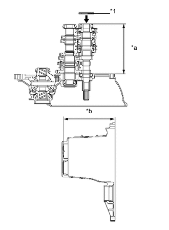
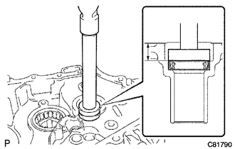
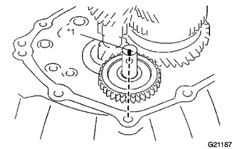
Text in Illustration *1 Rear Input Shaft Bearing Shim *a Dimension A *b Dimension B Using a vernier caliper, accurately measure dimensions A and B shown in the illustration.
-
Calculate the rear input shaft bearing shim clearance using the following formula.
Formula Dimension B - Dimension A - Rear input shaft bearing shim thickness = Between 0 mm and 0.1 mm (0.00394 in.) If the clearance is not as specified, replace the rear input shaft bearing shim with one of a different thickness. Use the table below to select a rear input shaft bearing shim which will ensure that the clearance is within the specification.
Plate Washer Thickness Part No. Mark Thickness
mm (in.)
90564-38006 F 1.800 (0.0709) 90564-38007 G 1.850 (0.0728) 90564-38008 H 1.900 (0.0748) 90564-38009 J 1.950 (0.0768) 90564-38010 K 2.000 (0.0787) 90564-38011 L 2.050 (0.0807) 90564-38012 M 2.100 (0.0827) 90564-38013 N 2.150 (0.0846) 90564-38014 P 2.200 (0.0866) 90564-38015 Q 2.250 (0.0886) 90564-38016 R 2.300 (0.0906) 90564-38017 S 2.350 (0.0925) 90564-38018 T 2.400 (0.0945) -
Coat the selected rear input shaft bearing shim with MP grease, and then replace the installed rear input shaft bearing shim with the selected one.
-
-
INSTALL TRANSMISSION CASE OIL SEAL
-
INSTALL TRANSAXLE CASE OIL SEAL
-
INSTALL FRONT TRANSAXLE CASE OIL SEAL
-
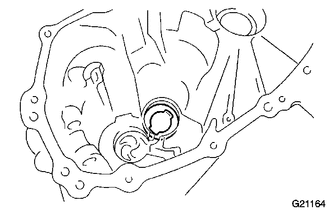
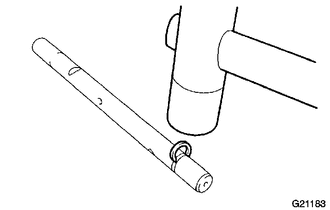
Using SST and a hammer, install a new front transaxle case oil seal to the front transaxle case.
- SST
- 09710-20011 ( 09710-06071 )
- 09950-70010 ( 09951-07150 )
Standard depth 14.4 to 14.9 mm (0.567 to 0.586 in.) Note
Do not damage the lip of the oil seal.
-
Coat the tip of the front transaxle case oil seal with MP grease.
-
-
INSTALL TRANSMISSION MAGNET
-
Clean the transmission magnet and install it to the front transaxle case.
-
-
INSTALL NO. 2 OIL RECEIVER PIPE
-
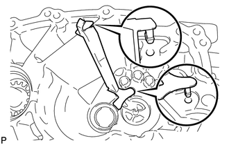
Align the 2 protrusions with the 2 holes of the manual transmission case and install the No. 2 oil receiver pipe to the manual transmission case as shown in the illustration.
Note
Do not damage the No. 2 oil receiver pipe.
-
-
INSTALL DIFFERENTIAL CASE ASSEMBLY
-
Coat the differential case tapered roller bearing with gear oil, and install it to the front transaxle case.
-
-
INSTALL OUTPUT SHAFT ASSEMBLY
-
Install the output shaft assembly to the front transaxle case.
-
-
INSTALL INPUT SHAFT ASSEMBLY
-
Coat the sliding and rotating surfaces of the input shaft assembly and output shaft assembly with gear oil and install them to the front transaxle case.
Note
Do not damage the lip of the front transaxle case oil seal.
-
-
INSTALL NO. 2 GEAR SHIFT FORK SHAFT
-
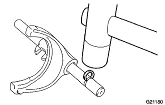
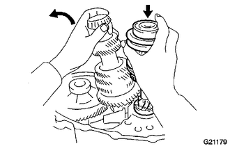
Install the No. 2 gear shift fork to the No. 2 gear shift fork shaft.
-
Using a plastic-faced hammer, install a new snap ring to the No. 2 gear shift fork shaft.
-
Install the reverse shift fork to No. 2 gear shift fork shaft.
-
Shift the No. 2 transmission clutch hub sleeve to the 4th gear position.
-
While aligning the No. 2 gear shift fork with the No. 2 transmission hub sleeve, install the No. 2 gear shift fork shaft together with the No. 2 gear shift fork and reverse shift fork to the front transaxle case.
-
Coat the gear shift fork No. 2 bolt with adhesive.
Adhesive Toyota Genuine Adhesive 1324, Three Bond 1324 or equivalent -
Install the No. 2 gear shift fork bolt to the No. 2 gear shift fork.
- Torque:
- 16 N*m { 160 kgf*cm, 12 ft.*lbf }
-
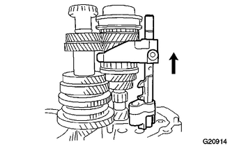
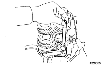
While lifting the reverse shift fork, using a brass bar and hammer, install a new snap ring to the No. 2 gear shift fork shaft.
-
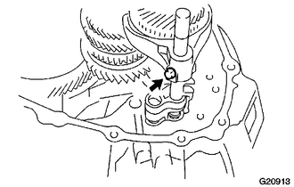
Install the straight pin to the reverse shift fork.
-
-
INSTALL NO. 3 GEAR SHIFT FORK SHAFT
-
Install the No. 3 gear shift fork to the No. 3 transmission hub sleeve.
-
Using a hammer, tap a new snap ring to the No. 3 gear shift fork shaft.
-
Pass the No. 3 gear shift fork shaft through the No. 3 gear shift fork, compression spring and No. 3 gear shift head, and then install them to the front transaxle case.
-
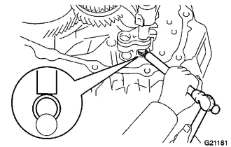
Using a pin punch and hammer, tap in the slotted spring pin to the No. 3 gear shift head to secure the No. 3 gear shift head to the No. 3 gear shift fork shaft.
-
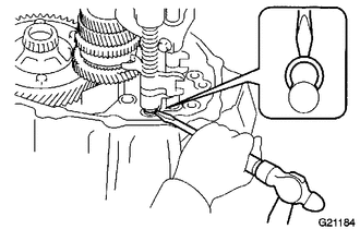
Using a screwdriver and a hammer, install a new snap ring to the No. 3 gear shift fork shaft.
-
Install the straight pin to the No. 3 gear shift fork.
-
-
INSTALL NO. 1 GEAR SHIFT FORK SHAFT
-
Install the No. 1 gear shift fork to the No. 1 transmission hub sleeve.
-
Using a hammer, install a new snap ring to the No. 1 gear shift fork shaft.
-
Pass the No. 1 gear shift fork shaft through the No. 1 gear shift head and No. 1 gear shift fork, and then install them to the front transaxle case.
-
Using a pin punch and hammer, tap in the slotted spring pin to the No. 1 gear shift head to secure the No. 1 gear shift head to the No. 1 gear shift fork shaft.
-
Coat the gear shift fork No. 1 bolt with adhesive.
Adhesive Toyota Genuine Adhesive 1324, Three Bond 1324 or equivalent -
Install the No. 1 gear shift fork bolt to the No.1 gear shift fork.
- Torque:
- 16 N*m { 160 kgf*cm, 12 ft.*lbf }
-
-
INSTALL REVERSE IDLER GEAR SUB-ASSEMBLY
-
Coat the reverse idler gear shaft with gear oil.
-
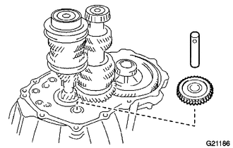
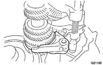
Install the reverse idler gear sub-assembly to the front transaxle case, and then pass the reverse idler gear shaft through the reverse idler gear sub-assembly to install it.
-
Text in Illustration *1 Alignment Mark Align the alignment mark on the reverse idler gear shaft with the bolt hole of the front transaxle case as shown in the illustration.
-
-
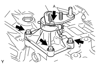
INSTALL REVERSE SHIFT ARM BRACKET ASSEMBLY
-
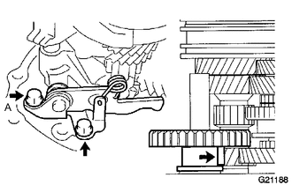
Coat the bolt A with adhesive.
Adhesive Toyota Genuine Adhesive 1324, Three Bond 1324 or equivalent -
Install the reverse shift arm bracket assembly to the front transaxle case with the 2 bolts.
- Torque:
- 17 N*m { 175 kgf*cm, 13 ft.*lbf }
-
-
INSTALL MANUAL TRANSMISSION CASE
-
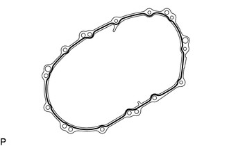
the manual transmission case as shown in the illustration.
Seal packing Toyota Genuine Seal Packing 1281, Three Bond 1281 or equivalent Note
-
Remove any oil from the contact surfaces.
-
Assemble parts within 10 minutes of application. Otherwise, the packing material must be removed and reapplied.
-
-
Install the manual transmission case to the front transaxle case with the 13 bolts.
Tech Tips
From manual transmission case side: 8 bolts
From front transaxle case side: 5 bolts
- Torque:
- 29 N*m { 300 kgf*cm, 22 ft.*lbf }
-
-
INSTALL REVERSE IDLER GEAR SHAFT BOLT
-
Coat the reverse idler gear shaft bolt with adhesive, and install it with a new gasket.
Adhesive Toyota Genuine Adhesive 1324, Three Bond 1324 or equivalent - Torque:
- 29 N*m { 300 kgf*cm, 22 ft.*lbf }
-
-
INSTALL SHIFT AND SELECT LEVER SHAFT ASSEMBLY
-
Install the select return compression spring to the manual transmission case.
-

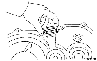
Apply seal packing to the control shaft cover of the shift and select lever shaft assembly as shown in the illustration.
Seal packing Toyota Genuine Seal Packing 1281, Three Bond 1281 or equivalent -
Coat the bolt A with adhesive.
Adhesive Toyota Genuine Adhesive 1324, Three Bond 1324 or equivalent -
Install the shift and select lever shaft assembly and 2 wire harness clamp brackets to the manual transmission case with the 4 bolts.
- Torque:
- 18 N*m { 184 kgf*cm, 13 ft.*lbf }
-
-
INSTALL SHIFT GATE PIN
-
Coat the shift gate pin with adhesive.
Adhesive Toyota Genuine Adhesive 1324, Three Bond 1324 or equivalent -
Install the shift gate pin onto the manual transmission case.
- Torque:
- 37 N*m { 375 kgf*cm, 27 ft.*lbf }
-
-
INSTALL CONTROL CABLE BRACKET
-
Coat the 2 bolts with adhesive.
Adhesive Toyota Genuine Adhesive 1324, Three Bond 1324 or equivalent -
Install the control cable bracket with the 2 bolts.
- Torque:
- 11 N*m { 115 kgf*cm, 8.3 ft.*lbf }
-
-
INSTALL BACK-UP LIGHT SWITCH ASSEMBLY
-
Using SST, install the back-up light switch with a new gasket onto the manual transmission case.
- SST
- 09817-16011
- Torque:
- 40 N*m { 410 kgf*cm, 30 ft.*lbf }
-
Engage the 2 clamps and connect the wire harness connector.
-
-
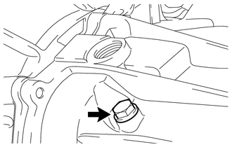
INSTALL MANUAL TRANSMISSION CASE PLUG
-
Install the manual transaxle case plug with a new gasket.
- Torque:
- 39 N*m { 400 kgf*cm, 29 ft.*lbf }
-
-
INSTALL CLUTCH RELEASE FORK LEVER
-
INSTALL CLUTCH RELEASE BEARING ASSEMBLY