MANUAL TRANSAXLE ASSEMBLY INSTALLATION
PROCEDURE
-
INSTALL SPEEDOMETER DRIVEN HOLE COVER SUB-ASSEMBLY (for AISIN AI Made)
-
Apply a light coat of gear oil to a new O-ring and install it to the speedometer driven hole cover sub-assembly.
Note
Be careful not to damage or twist the O-ring.
-
Install the speedometer driven hole cover sub-assembly to the manual transaxle assembly with bolt.
- Torque:
- 11 N*m { 115 kgf*cm, 8 ft.*lbf }
Note
Make sure that the O-ring is not damaged or does not jump out of position during installation.
-
-
INSTALL MANUAL TRANSMISSION CASE PLUG (for TMMP Made)
-
Install a new gasket and manual transaxle case plug to the manual transaxle assembly.
- Torque:
- 39 N*m { 400 kgf*cm, 29 ft.*lbf }
-
-
INSTALL WIRE HARNESS CLAMP BRACKET
-
Install the 2 wire harness clamp brackets to the manual transaxle assembly with the 2 bolts.
- Torque:
- 13 N*m { 130 kgf*cm, 9 ft.*lbf }
-
-
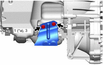
INSTALL SHIFT LEVER DAMPER
-
Install the shift lever damper to the manual transaxle assembly with the 2 nuts.
- Torque:
- 20 N*m { 204 kgf*cm, 15 ft.*lbf }
-
-
INSTALL MANUAL TRANSAXLE ASSEMBLY
-
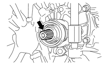
Apply clutch spline grease to the input shaft spline.
Text in Illustration 
Clutch Spline Grease Grease Toyota Genuine Clutch Spline Grease or equivalent -
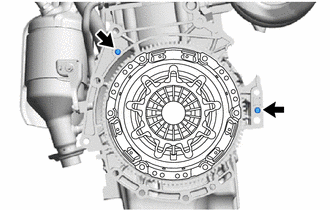
Confirm that the 2 knock pins are installed on the engine assembly and are not damaged.
-
Align the input shaft with the clutch disc and install the manual transaxle assembly to the engine assembly.
-
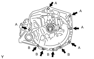
Install the 9 bolts.
- Torque:
- Bolt A
- 64 N*m { 653 kgf*cm, 47 ft.*lbf }
- Bolt B
- 39 N*m { 398 kgf*cm, 29 ft.*lbf }
Note
-
Make sure that the wire harness or similar items are not pinched between the contact surfaces.
-
Do not forcibly pry on the manual transaxle assembly.
-
When mounting the manual transaxle assembly to the engine assembly, make sure to securely fit the knock pins into the knock holes.
-
When tightening the bolts, be sure that the contact surfaces of the engine assembly and manual transaxle assembly are in close contact with one another.
-
-
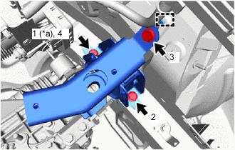
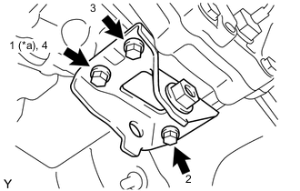
INSTALL ENGINE MOUNTING BRACKET LH
-
Clean and degrease the bolts and bolt holes.
-
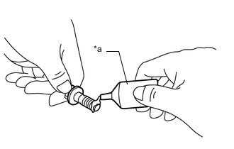
Text in Illustration *a Adhesive Apply adhesive to 2 or 3 threads on the ends of the 4 bolts.
Adhesive Toyota Genuine Adhesive 1324, Three Bond 1324 or equivalent Note
To prevent contamination by foreign matter, install immediately after applying adhesive.
-
Text in Illustration *a Temporarily Tighten Install the engine mounting bracket LH to the manual transaxle assembly with the 4 bolts in the order shown in the illustration.
- Torque:
- 64 N*m { 653 kgf*cm, 47 ft.*lbf }
-
-
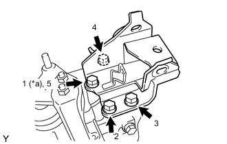
INSTALL ENGINE MOUNTING INSULATOR LH
-
Text in Illustration *a Temporarily Tighten Engage the hook to temporarily install the engine mounting insulator LH to the body.
-
Install the 3 bolts in the order shown in the illustration.
- Torque:
- 52 N*m { 530 kgf*cm, 38 ft.*lbf }
-
Install the engine mounting insulator LH to the engine mounting bracket LH with the bolt, through bolt and nut.
- Torque:
- Bolt
- 64 N*m { 653 kgf*cm, 47 ft.*lbf }
- Through Bolt
- 52 N*m { 530 kgf*cm, 38 ft.*lbf }
Note
Install the bolt first and then the through bolt and nut.
Tech Tips
Turn the through bolt while holding the nut.
-
-
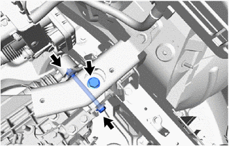
INSTALL ENGINE MOVING CONTROL ROD BRACKET
-
Text in Illustration *a Temporarily Tighten Install the engine moving control rod bracket to the manual transaxle assembly with the 3 bolts in the order shown in the illustration.
- Torque:
- 45 N*m { 459 kgf*cm, 33 ft.*lbf }
-
-
INSTALL FRONT SUSPENSION CROSSMEMBER SUB-ASSEMBLY
-
INSTALL STARTER ASSEMBLY
-
INSTALL FLYWHEEL HOUSING SIDE COVER
-
INSTALL FRONT DRIVE SHAFT ASSEMBLIES
-
INSTALL DRIVE SHAFT HEAT INSULATOR SUB-ASSEMBLY
-
Text in Illustration *a Temporarily Tighten Install the drive shaft heat insulator sub-assembly to the engine assembly with the 2 bolts in the order shown in the illustration.
- Torque:
- 24 N*m { 240 kgf*cm, 17 ft.*lbf }
-
-
INSTALL FRONT EXHAUST PIPE ASSEMBLY
-
INSTALL FRONT FLOOR CENTER BRACE
-
INSTALL NO. 1 STEERING COLUMN HOLE COVER SUB-ASSEMBLY
-
CONNECT STEERING INTERMEDIATE SHAFT ASSEMBLY
-
INSTALL COLUMN HOLE COVER SILENCER SHEET
-
INSTALL CLUTCH RELEASE CYLINDER ASSEMBLY
-
Install the clutch release cylinder assembly to the manual transaxle assembly with the 4 bolts.
- Torque:
- Bolt A for AISIN AI Made
- 12 N*m { 120 kgf*cm, 9 ft.*lbf }
- Bolt A for TMMP Made
- 14 N*m { 141 kgf*cm, 10 ft.*lbf }
- Bolt B
- 19 N*m { 194 kgf*cm, 14 ft.*lbf }
-
-
INSTALL RELEASE CYLINDER HEAT INSULATOR
-
Install the release cylinder heat insulator to the clutch release cylinder assembly with the 2 bolts.
- Torque:
- 12 N*m { 120 kgf*cm, 9 ft.*lbf }
-
-
CONNECT ENGINE WIRE
-
Engage the 2 clamps to install the engine wire to the wire harness clamp brackets.
-
Connect the back-up light switch assembly connector.
-
w/ Stop and Start System:
-
Install the wire harness clamp bracket to the clutch flexible hose bracket with the bolt.
- Torque:
- 13 N*m { 130 kgf*cm, 9 ft.*lbf }
-
Engage the 2 clamps to install the engine wire to the wire harness clamp bracket.
-
Connect the neutral position switch connector.
-
-
-
CONNECT NO. 3 ENGINE WIRE
-
Engage the 2 clamps to install the No. 3 engine wire to the engine mounting bracket LH.
-
Connect the No. 3 engine wire to the manual transaxle assembly with the bolt.
- Torque:
- 26 N*m { 260 kgf*cm, 19 ft.*lbf }
-
-
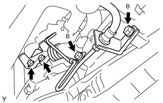
INSTALL TRANSMISSION CONTROL CABLE ASSEMBLY
-
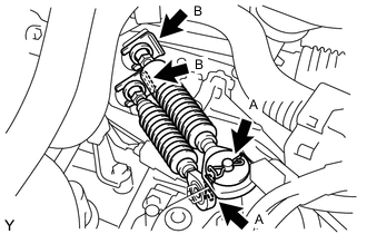
Install the transmission control cable assembly to the control cable bracket with 2 new clips B.
-
Connect the transmission control cable assembly to the manual transaxle assembly with the 2 clips A.
-
-
INSTALL BATTERY CARRIER
-
INSTALL BATTERY TRAY
-
INSTALL BATTERY
-
ADD MANUAL TRANSAXLE OIL
-
CONNECT CABLE TO NEGATIVE BATTERY TERMINAL
- Torque:
- 5.4 N*m { 55 kgf*cm, 48 in.*lbf }
Note
When disconnecting the cable, some systems need to be initialized after the cable is reconnected Click here.
-
INSPECT SPEED SENSOR SIGNAL
-
INSPECT AND ADJUST FRONT WHEEL ALIGNMENT
-
INSPECT FOR EXHAUST GAS LEAK
-
INSPECT MANUAL TRANSAXLE OIL LEVEL
-
INSPECT FOR MANUAL TRANSMISSION OIL LEAK
-
INSTALL ENGINE UNDER COVER RH
- Torque:
- 5.0 N*m { 51 kgf*cm, 44 in.*lbf }
-
INSTALL ENGINE UNDER COVER LH
- Torque:
- 5.0 N*m { 51 kgf*cm, 44 in.*lbf }