MANUAL TRANSAXLE ASSEMBLY INSTALLATION
PROCEDURE
-
INSTALL SPEEDOMETER DRIVEN HOLE COVER SUB-ASSEMBLY (for TMC Made)
-
Apply manual transaxle oil to a new O-ring and install it to the speedometer driven hole cover sub-assembly.
-
Install the speedometer driven hole cover sub-assembly to the transaxle case with bolt.
- Torque:
- 11 N*m { 115 kgf*cm, 8 ft.*lbf }
-
-
INSTALL MANUAL TRANSMISSION CASE PLUG (for TMMF Made)
-
Install the manual transaxle case plug and gasket to the transaxle case.
- Torque:
- 39 N*m { 400 kgf*cm, 29 ft.*lbf }
-
-
INSTALL WIRE HARNESS CLAMP BRACKET
-
Install the 2 wire harness clamp brackets with the 2 bolts.
- Torque:
- 13 N*m { 130 kgf*cm, 9 ft.*lbf }
-
-
INSTALL SHIFT LEVER DAMPER
-
Install the shift lever damper with the 2 nuts.
- Torque:
- 20 N*m { 204 kgf*cm, 15 ft.*lbf }
-
-
INSTALL MANUAL TRANSAXLE ASSEMBLY
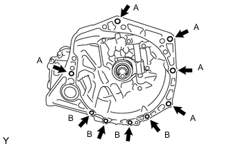
-
Align the input shaft with the clutch disc and install the manual transaxle onto the engine.
-
Install the 9 bolts.
- Torque:
- Bolt A
- 64 N*m { 653 kgf*cm, 47 ft.*lbf }
- Bolt B
- 39 N*m { 398 kgf*cm, 29 ft.*lbf }
Note
-
Insert dowel pins into dowel holes securely so that the end face of transaxle assembly fits close against engine assembly before tightening the bolts between the engine and transaxle.
-
Make sure that the dowel pins are not loose, bent, damaged or scratched and then install the transaxle onto the engine with the contact surfaces of the engine and transaxle flat against each other.
-
-
INSTALL ENGINE MOUNTING BRACKET LH
-
Clean and degrease the bolt and the bolt installation hole.
-
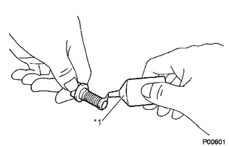
Text in Illustration *1 Adhesive Apply adhesive to 2 or 3 threads of the bolt end.
Adhesive Toyota Genuine Adhesive 1324, Three Bond 1324 or equivalent -
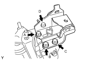
Install the engine mounting bracket LH with the 4 bolts in several steps.
- Torque:
- 64 N*m { 653 kgf*cm, 47 ft.*lbf }
Note
Temporarily tighten bolt A, and then fully tighten the 4 bolts in the order of B, C, D and A.
-
-
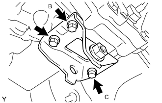
INSTALL ENGINE MOUNTING INSULATOR LH
-
Install the engine mounting insulator LH with the 3 bolts.
- Torque:
- 52 N*m { 530 kgf*cm, 38 ft.*lbf }
Note
Temporarily tighten bolt A and B or C, and then fully tighten the 3 bolts in the order of A, B and C.
-
Install the engine mounting insulator LH to the engine mounting bracket LH with the 2 bolts and nut.
- Torque:
- Bolt A
- 64 N*m { 653 kgf*cm, 47 ft.*lbf }
- Bolt B
- 52 N*m { 530 kgf*cm, 38 ft.*lbf }
Note
Turn the bolt while holding the nut.
-
-
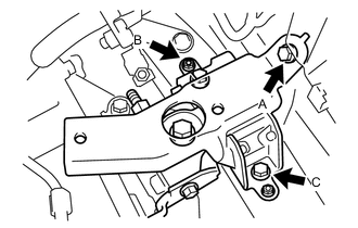
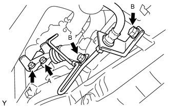
INSTALL ENGINE MOVING CONTROL ROD BRACKET
-
Install the engine moving control rod bracket with the 3 bolts in several steps.
- Torque:
- 45 N*m { 459 kgf*cm, 33 ft.*lbf }
Note
Temporarily tighten bolt A, and then fully tighten the 3 bolts in the order of B, C, and A.
-
-
INSTALL FRONT SUSPENSION CROSSMEMBER SUB-ASSEMBLY
-
INSTALL FRONT EXHAUST PIPE ASSEMBLY
-
CONNECT NO. 2 OXYGEN SENSOR CONNECTOR
-
INSTALL FRONT DRIVE SHAFT ASSEMBLY
-
INSTALL STARTER ASSEMBLY (for TMC Made)
-
INSTALL STARTER ASSEMBLY (for TMMF Made)
-
ADD MANUAL TRANSAXLE OIL
-
INSTALL ENGINE UNDER COVER LH
-
Install the engine under cover LH.
- Torque:
- 5.0 N*m { 51 kgf*cm, 44 in.*lbf }
-
-
INSTALL ENGINE UNDER COVER RH
-
Install the engine under cover RH.
- Torque:
- 5.0 N*m { 51 kgf*cm, 44 in.*lbf }
-
-
INSTALL STEERING SLIDING YOKE SUB-ASSEMBLY (for LHD)
-
INSTALL STEERING SLIDING YOKE SUB-ASSEMBLY (for RHD)
-
INSTALL COLUMN HOLE COVER SILENCER SHEET (for LHD)
-
INSTALL COLUMN HOLE COVER SILENCER SHEET (for RHD)
-
INSTALL TRANSMISSION CONTROL CABLE ASSEMBLY (for TMC Made)
-
Install the 2 cables to the control cable bracket with 2 new clips.
-
Connect the 2 cables to the transaxle and install the 2 washers and the 2 clips.
-
-
INSTALL TRANSMISSION CONTROL CABLE ASSMBLY (for TMMF Made)
-
Install the 2 cables to the control cable bracket with 2 new clips.
-
Connect the 2 cables to the transaxle and install the 2 clips.
-
-
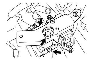
INSTALL CLUTCH RELEASE CYLINDER ASSEMBLY
-
Install the clutch release cylinder and clutch pipe with the 4 bolts.
- Torque:
- Bolt A for TMC Made
- 12 N*m { 120 kgf*cm, 9 ft.*lbf }
- Bolt A for TMMF Made
- 14 N*m { 141 kgf*cm, 10 ft.*lbf }
- Bolt B
- 19 N*m { 194 kgf*cm, 14 ft.*lbf }
-
-
INSTALL RELEASE CYLINDER HEAT INSULATOR
-
Install the release cylinder heat insulator with the 2 bolts.
- Torque:
- 12 N*m { 120 kgf*cm, 8.7 ft.*lbf }
-
-
CONNECT WIRE HARNESS
-
Connect the back-up light switch connector.
-
Engage the 2 clamps and connect the 2 wire harnesses.
-
Engage the wire harness clamp.
-
Connect the wire harness to manual transaxle assembly with the bolt.
- Torque:
- 26 N*m { 260 kgf*cm, 19 ft.*lbf }
-
-
INSTALL BATTERY CARRIER (for LHD)
-
INSTALL BATTERY CARRIER (for RHD)
-
INSTALL BATTERY TRAY
-
INSTALL BATTERY
-
CONNECT CABLE TO NEGATIVE BATTERY TERMINAL
- Torque:
- 5.4 N*m { 55 kgf*cm, 48 in.*lbf }
-
INSPECT SPEED SENSOR SIGNAL
-
INSPECT AND ADJUST FRONT WHEEL ALIGNMENT
-
INSPECT FOR EXHAUST GAS LEAK
-
INSPECT MANUAL TRANSAXLE OIL LEVEL
-
INSPECT FOR MANUAL TRANSMISSION OIL LEAK