MANUAL TRANSAXLE ASSEMBLY REMOVAL
PROCEDURE
-
PRECAUTION
Note
After turning the ignition switch off, waiting time may be required before disconnecting the cable from the battery terminal. Therefore, make sure to read the disconnecting the cable from the battery terminal notice before proceeding with work Click here.
-
DISCONNECT CABLE FROM NEGATIVE BATTERY TERMINAL
Note
When disconnecting the cable, some systems need to be initialized after the cable is reconnected Click here.
-
REMOVE ENGINE UNDER COVER LH
-
REMOVE ENGINE UNDER COVER RH
-
DRAIN MANUAL TRANSAXLE OIL
-
REMOVE BATTERY
-
REMOVE BATTERY TRAY
-
REMOVE BATTERY CARRIER
-
DISCONNECT TRANSMISSION CONTROL CABLE ASSEMBLY
-
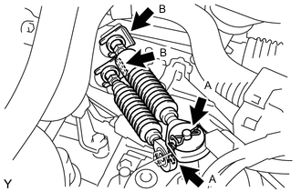
Remove the 2 clips A to disconnect the transmission control cable assembly from the manual transaxle assembly.
-
Remove the 2 clips B to separate the transmission control cable assembly from the control cable bracket.
-
-
DISCONNECT NO. 3 ENGINE WIRE
-
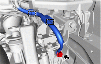
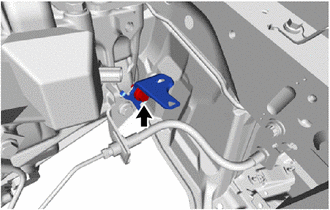
Remove the bolt to disconnect the No. 3 engine wire from the manual transaxle assembly.
-
Disengage the 2 clamps to separate the No. 3 engine wire from the engine mounting bracket LH.
-
-
DISCONNECT ENGINE WIRE
-
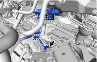
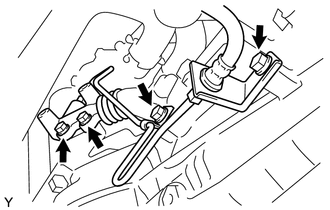
Disconnect the back-up light switch assembly connector.
-
Disengage the 2 clamps to separate the engine wire from the wire harness clamp brackets.
-
w/ Stop and Start System:
-
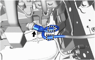
Disconnect the neutral position switch connector.
-
Disengage the 2 clamps to separate the engine wire from the wire harness clamp bracket.
-
Remove the bolt and wire harness clamp bracket from the clutch flexible hose bracket.
-
-
-
REMOVE RELEASE CYLINDER HEAT INSULATOR
-
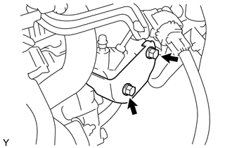
Remove the 2 bolts and release cylinder heat insulator from the clutch release cylinder assembly.
-
-
SEPARATE CLUTCH RELEASE CYLINDER ASSEMBLY
-
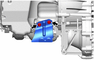
Remove the 4 bolts to separate the clutch release cylinder assembly from the manual transaxle assembly.
Note
-
Suspend the clutch release cylinder assembly with a piece of rope so as not to place stress on the clutch line.
-
Do not depress the clutch pedal.
-
-
-
REMOVE COLUMN HOLE COVER SILENCER SHEET
-
DISCONNECT STEERING INTERMEDIATE SHAFT ASSEMBLY
-
SEPARATE NO. 1 STEERING COLUMN HOLE COVER SUB-ASSEMBLY
-
REMOVE FRONT FLOOR CENTER BRACE
-
REMOVE FRONT EXHAUST PIPE ASSEMBLY
-
REMOVE DRIVE SHAFT HEAT INSULATOR SUB-ASSEMBLY
-
Remove the 2 bolts and drive shaft heat insulator sub-assembly from the engine assembly.
-
-
REMOVE FRONT DRIVE SHAFT ASSEMBLIES
-
REMOVE FLYWHEEL HOUSING SIDE COVER
-
REMOVE STARTER ASSEMBLY
-
SUPPORT ENGINE ASSEMBLY
-
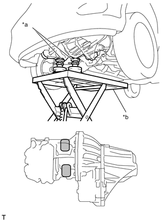
Text in Illustration *a Attachment *b Engine Lifter 
Attachment Placement Positions Place the height adjustment attachments or plate lift attachments in the positions shown in the illustration and set the engine lifter underneath the engine assembly.
Note
-
Place the height adjustment attachments or plate lift attachments so that the engine assembly with the manual transaxle assembly is level.
-
As the engine assembly with the manual transaxle assembly is very heavy, be sure to support it securely.
-
-
-
REMOVE FRONT SUSPENSION CROSSMEMBER SUB-ASSEMBLY
-
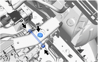
REMOVE ENGINE MOVING CONTROL ROD BRACKET
-
Remove the 3 bolts and engine moving control rod bracket from the manual transaxle assembly.
-
-
SUPPORT MANUAL TRANSAXLE ASSEMBLY
-
Support the manual transaxle assembly with a transmission jack so that it is stable.
-
-
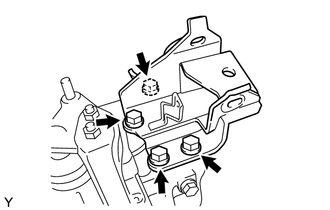
REMOVE ENGINE MOUNTING INSULATOR LH
-
Remove the bolt, through bolt and nut to separate the engine mounting insulator LH from the engine mounting bracket LH.
Tech Tips
Turn the through bolt while holding the nut.
-
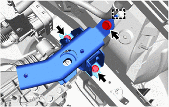
Remove the 3 bolts.
-
Disengage the hook to remove the engine mounting insulator LH from the body.
-
-
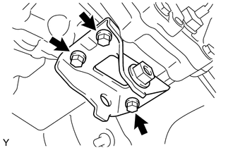
REMOVE ENGINE MOUNTING BRACKET LH
-
Remove the 4 bolts and engine mounting bracket LH from the manual transaxle assembly.
-
-
REMOVE MANUAL TRANSAXLE ASSEMBLY
-
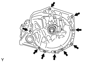
Remove the 9 bolts and manual transaxle assembly from the engine assembly.
Note
-
To prevent damage to the knock pins, do not pry between the manual transaxle assembly and engine assembly.
-
To prevent damage to the input shaft, do not forcefully shake the manual transaxle assembly.
-
-
-
REMOVE SHIFT LEVER DAMPER
-
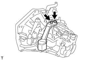
Remove the 2 nuts and shift lever damper from the manual transaxle assembly.
-
-
REMOVE WIRE HARNESS CLAMP BRACKET
-
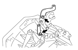
Remove the 2 bolts and 2 wire harness clamp brackets from the manual transaxle assembly.
-
-
REMOVE SPEEDOMETER DRIVEN HOLE COVER SUB-ASSEMBLY (for AISIN AI Made)
-
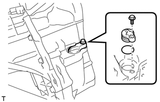
Remove the bolt and speedometer driven hole cover sub-assembly from the manual transaxle assembly.
-
Remove the O-ring from the speedometer driven hole cover sub-assembly.
-
-
REMOVE MANUAL TRANSMISSION CASE PLUG (for TMMP Made)
-
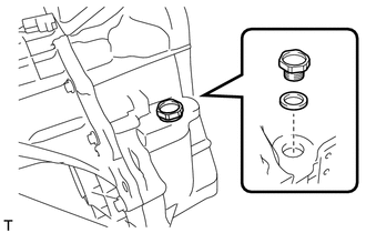
Remove the manual transaxle case plug and gasket from the manual transaxle assembly.
-