SHIFT AND SELECT LEVER SHAFT REASSEMBLY

PROCEDURE
-
INSTALL CONTROL SHAFT COVER OIL SEAL
-
Coat the lip of a new control shaft cover oil seal with MP grease.
-
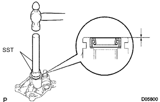
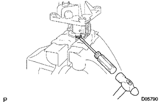
Using SST and a hammer, tap in the control shaft cover oil seal to the control shaft cover.
- SST
- 09950-60010 ( 09951-00260 )
- 09950-70010 ( 09951-07100 )
Standard depth 0 to 0.5 mm (0 to 0.0196 in.) Note
Be careful not to damage the lip of the control shaft cover oil seal.
-
-
INSTALL SELECT LEVER SHAFT OIL SEAL
-
Coat the lip of a new select lever shaft oil seal with MP grease.
-
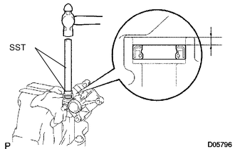
Using SST and a hammer, tap in the select lever shaft oil seal to the control shaft cover.
- SST
- 09950-60010 ( 09951-00240 )
- 09950-70010 ( 09951-07100 )
Standard depth 2.0 to 2.5 mm (0.0788 to 0.0984 in.) Note
Be careful not to damage the lip of the select lever shaft oil seal.
-
-
INSTALL SHIFT AND SELECT LEVER SHAFT
-
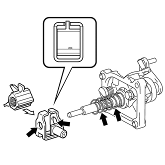
Apply MP grease to the contact surface of the shift lever boot and install the shift lever boot to the shift and select lever shaft.
Text in Illustration 
MP grease -
Apply MP grease to the contact surfaces of the control shaft cover and shift and select lever shaft.
-
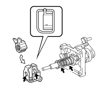
Install the shift and select lever shaft together with the shift lever boot to the control shaft cover.
Note
Be careful not to damage the lip of the control shaft cover oil seal.
-
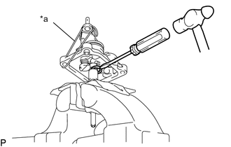
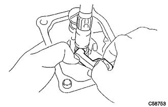
Text in Illustration *a Rope or equivalent Using a screwdriver and hammer, install a new snap ring to the shift and select lever shaft.
Tech Tips
Lifting the control shaft cover up with a piece of rope or the equivalent makes the work easier.
-
-
INSTALL SELECT INNER LEVER
-
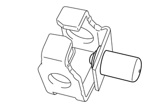
Install the select inner lever to the control shaft cover.
-
-
INSTALL SELECT LEVER SHAFT
-
Apply MP grease to the contact surfaces of the control shaft cover and select lever shaft.
-
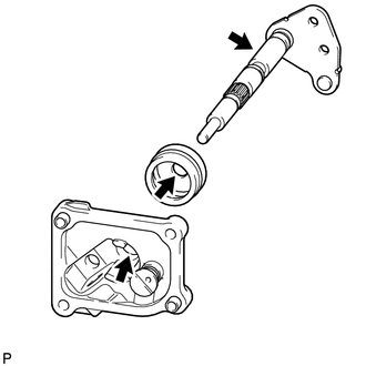
Install the select lever shaft to the control shaft cover and pass the select lever shaft through the select inner lever.
Note
-
Be careful not to damage the lip of the select lever shaft oil seal.
-
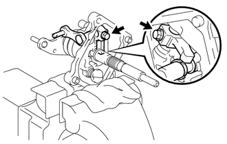
Fit the end of the select inner lever into the groove of the shift and select lever shaft as shown in the illustration.
-
-
Clean and degrease the bolt and installation hole in the select lever shaft.
-
Coat the threads of the bolt with adhesive and install it to the select inner lever.
Adhesive Toyota Genuine Adhesive 1324, Three Bond 1324 or equivalent - Torque:
- 38 N*m { 387 kgf*cm, 28 ft.*lbf }
Note
To prevent contamination by foreign matter, install immediately after applying adhesive.
-
-
INSTALL NO. 2 SELECT SPRING SEAT
-
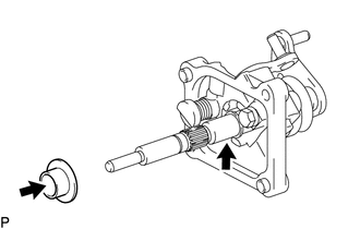
Apply MP grease to the inner surface of the No. 2 select spring seat and shift and select lever shaft, and then install the No. 2 select spring seat to the shift and select lever shaft.
Text in Illustration MP grease
-
-
INSTALL SELECT RETURN COMPRESSION SPRING
-
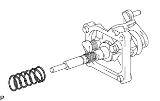
Install the select return compression spring to the shift and select lever shaft.
-
-
INSTALL LOCK BALL HOLDER
-
Install the lock ball pin and spring to the lock ball holder.
-
Install the lock ball holder to the shift interlock plate.
-
-
INSTALL INNER NO. 1 SHIFT LEVER (w/o Stop and Start System)
-
Apply MP grease to the contact surfaces of the shift interlock plate and shift and select lever shaft.
Text in Illustration MP grease -
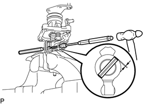
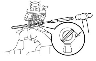
While pushing up the inner No. 1 shift lever so that the hole of the inner No. 1 shift lever aligns with the hole of the shift and select lever shaft, insert a 5 mm pin punch halfway into the inner No. 1 shift lever, and then using another 5 mm pin punch and a hammer, tap in the inner No. 1 shift lever slotted pin. When the inner No. 1 shift lever is fixed in place with the slotted spring pin, pull out the pin punch while holding the inner No. 1 shift lever.
Standard depth -0.5 to 0.5 mm (-0.0196 to 0.0196 in.) -
Using a screwdriver and hammer, install a new snap ring to the shift and select lever shaft.
-
-
INSTALL INNER NO. 1 SHIFT LEVER (w/ Stop and Start System)
-
Apply MP grease to the contact surfaces of the shift interlock plate and shift and select lever shaft.
Text in Illustration MP grease -
While pushing up the inner No. 1 shift lever so that the hole of the inner No. 1 shift lever aligns with the hole of the shift and select lever shaft, insert a 5 mm pin punch halfway into the inner No. 1 shift lever, and then using another 5 mm pin punch and a hammer, tap in the inner No. 1 shift lever slotted pin. When the inner No. 1 shift lever is fixed in place with the slotted spring pin, pull out the pin punch while holding the inner No. 1 shift lever.
Standard depth -0.5 to 0.5 mm (-0.0196 to 0.0196 in.)
-