SHIFT AND SELECT LEVER SHAFT REASSEMBLY

PROCEDURE
-
INSTALL CONTROL SHAFT COVER OIL SEAL
-
Coat the lip of a new control shaft cover oil seal with MP grease.
-
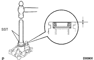
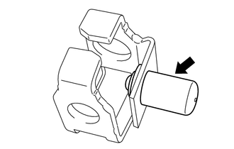
Using SST and a hammer, tap in the control shaft cover oil seal to the control shaft cover.
- SST
- 09950-60010 ( 09951-00260 )
- 09950-70010 ( 09951-07100 )
Standard depth 0 to 0.5 mm (0 to 0.020 in.) Note
Do not damage the lip of the control shaft cover oil seal.
-
-
INSTALL SELECT LEVER SHAFT OIL SEAL
-
Coat the lip of a new select lever shaft oil seal with MP grease.
-
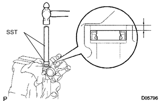
Using SST and a hammer, tap in the select lever shaft oil seal to the control shaft cover.
- SST
- 09950-60010 ( 09951-00240 )
- 09950-70010 ( 09951-07100 )
Standard depth 2.0 to 2.5 mm (0.0788 to 0.0984 in.) Note
Do not damage the lip of the select lever shaft oil seal.
-
-
INSTALL SHIFT AND SELECT LEVER SHAFT
-
Text in Illustration *1 MP grease Apply MP grease to the contact surface of the shift lever boot and install the shift lever boot to the shift and select lever shaft.
-
Apply MP grease to the contact surfaces of the control shaft cover and shift and select lever shaft.
-
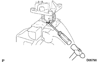
Install the shift and select lever shaft together with the shift lever boot to the control shaft cover.
Note
Do not damage the lip of the oil seal.
-
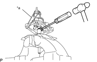
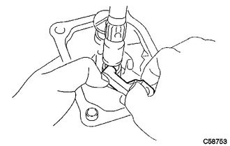
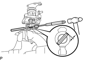
Text in Illustration *a Rope or equivalent Using a screwdriver and hammer, install a new snap ring to the shift and select lever shaft.
Tech Tips
Lifting the control shaft cover up with a piece of rope or equivalent makes installation easier.
-
-
INSTALL SELECT INNER LEVER
-
Install the select inner lever to the control shaft cover.
-
-
INSTALL SELECT LEVER SHAFT
-
Apply MP grease to the contact surfaces of the control shaft cover and select lever shaft.
-
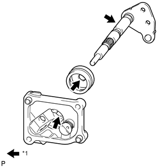
Install the select lever shaft to the control shaft cover and pass the select lever shaft through the select inner lever.
Note
-
Do not damage the lip of the select lever shaft oil seal.
-
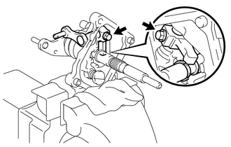
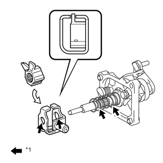
Fit the end of the select inner lever into the groove of the shift and select lever shaft as shown in the illustration.
-
-
Coat the threads of the bolts with adhesive and install the bolt to the select inner lever.
Adhesive Toyota Genuine Adhesive 1324, Three Bond 1324 or equivalent - Torque:
- 38 N*m { 387 kgf*cm, 28 ft.*lbf }
-
-
INSTALL NO. 2 SELECT SPRING SEAT
-
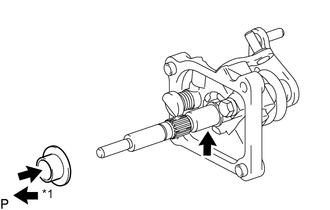
Text in Illustration *1 MP grease Apply MP grease to the inner surface of the No. 2 select spring seat and the shift and select lever shaft, and then install the No. 2 select spring seat to the shift and select lever shaft.
-
-
INSTALL SELECT RETURN COMPRESSION SPRING
-
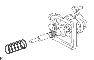
Install the select return compression spring to the shift and select lever shaft.
-
-
INSTALL LOCK BALL HOLDER
-
Install the lock ball holder.
-
-
INSTALL INNER NO. 1 SHIFT LEVER
-
Text in Illustration *1 MP grease Apply MP grease to the contact surfaces of the shift interlock plate and the shift and select lever shaft.
-
While pushing up the inner No. 1 shift lever so that the hole of the inner No. 1 shift lever aligns with the hole of the shift and select lever shaft, insert a pin punch halfway into the inner lever, and then using another pin punch and a hammer, tap in the inner No. 1 shift lever slotted pin. When the inner No. 1 shift lever is fixed in place with the slotted spring pin, pull out the pin punch while holding the inner lever.
Standard depth -0.5 to 0.5 mm (-0.0196 to 0.0196 in.) -
Using a screwdriver and hammer, install a new snap ring to the shift and select lever shaft.
-