CLUTCH PEDAL SWITCH INSTALLATION
PROCEDURE
-
INSTALL NO. 2 CLUTCH START SWITCH ASSEMBLY (for LHD)
-
Install the No. 2 clutch start switch assembly to the clutch pedal support sub-assembly and temporarily tighten the lock nut.
Tech Tips
Tighten the lock nut to the specified torque when adjusting the clutch pedal.
-
-
INSTALL NO. 2 CLUTCH START SWITCH ASSEMBLY (for RHD)
-
Install the No. 2 clutch start switch assembly to the clutch pedal support sub-assembly with the nut.
- Torque:
- 16 N*m { 160 kgf*cm, 12 ft.*lbf }
-
Connect the No. 2 clutch start switch connector.
-
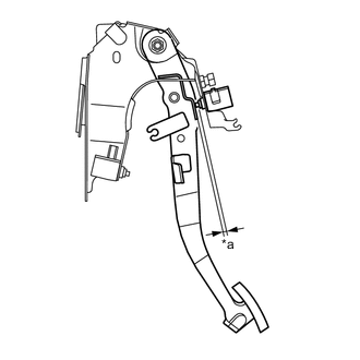
Text in Illustration *a Clearance Without depressing the clutch pedal, check that the clearance shown in the illustration is as specified.
Standard clearance except 1ND-TV 1.3 to 4.3 mm (0.0512 to 0.169 in.) for 1ND-TV 0.5 to 3.5 mm (0.0197 to 0.138 in.)
-
-
INSTALL CLUTCH START SWITCH ASSEMBLY
-
Install the clutch start switch assembly to the clutch pedal support sub-assembly with the nut.
- Torque:
- 16 N*m { 160 kgf*cm, 12 ft.*lbf }
-
Connect the clutch start switch connector.
-
With the clutch pedal fully depressed, check that the clearance shown in the illustration is as specified.
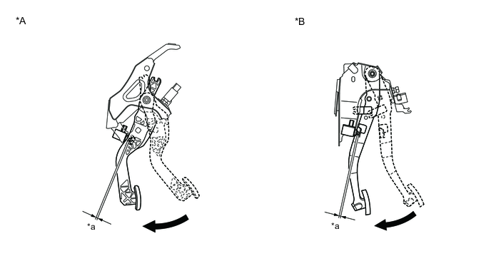
Text in Illustration *A for LHD *B for RHD *a Clearance 
Fully depressed Standard clearance for LHD except 1ND-TV 2.0 to 5.0 mm (0.0787 to 0.197 in.) for LHD 1ND-TV 2.5 to 5.5 mm (0.0984 to 0.217 in.) for RHD 2.5 to 5.5 mm (0.0984 to 0.217 in.)
-
-
INSPECT AND ADJUST CLUTCH PEDAL HEIGHT (for LHD)
-
INSTALL LOWER INSTRUMENT PANEL FINISH PANEL (w/o Knee Airbag)
-
INSTALL LOWER NO. 1 INSTRUMENT PANEL AIRBAG ASSEMBLY (w/ Knee Airbag)
-
INSTALL LOWER NO. 2 INSTRUMENT PANEL FINISH PANEL (for LHD)
-
INSTALL NO. 1 INSTRUMENT PANEL UNDER COVER SUB-ASSEMBLY
-
INSPECT CLUTCH START SYSTEM