CLUTCH PEDAL SWITCH INSPECTION
PROCEDURE
-
INSPECT CLUTCH START SWITCH ASSEMBLY
-
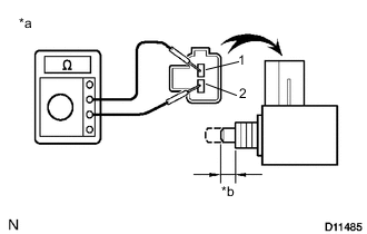
Text in Illustration *a Component without harness connected
(Clutch Start Switch Assembly)
*b 7.65 to 8.35 mm (0.301 to 0.329 in.) Measure the resistance according to the value(s) in the table below.
Standard Resistance Tester Connection Switch Condition Specified Condition 1 - 2 ON (Pushed in) Below 1 Ω OFF (Released) 10 kΩ or higher If the resistance is not as specified, replace the clutch start switch assembly.
-
-
INSPECT NO. 2 CLUTCH START SWITCH ASSEMBLY (for LHD)
-
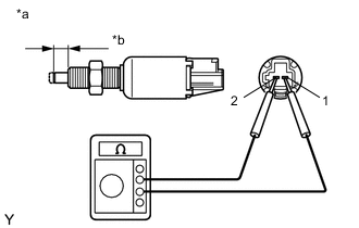
Text in Illustration *a Component without harness connected
(No. 2 Clutch Start Switch Assembly)
*b 6.5 to 7.5 mm (0.256 to 0.295 in.) Measure the resistance according to the value(s) in the table below.
Standard Resistance Tester Connection Switch Condition Specified Condition 1 - 2 ON (Pushed in) Below 1 Ω OFF (Released) 10 kΩ or higher If the resistance is not as specified, replace the No. 2 clutch start switch assembly.
-
-
INSPECT NO. 2 CLUTCH START SWITCH ASSEMBLY (for RHD)
-
Text in Illustration *a Component without harness connected
(No. 2 Clutch Start Switch Assembly)
*b 7.65 to 8.35 mm (0.301 to 0.329 in.) Measure the resistance according to the value(s) in the table below.
Standard Resistance Tester Connection Switch Condition Specified Condition 1 - 2 ON (Pushed in) Below 1 Ω OFF (Released) 10 kΩ or higher If the resistance is not as specified, replace the No. 2 clutch start switch assembly.
-