CLUTCH PEDAL(for RHD) INSTALLATION
PROCEDURE
-
INSTALL CLUTCH PEDAL PAD
-
Install the clutch pedal pad to the clutch pedal sub-assembly.
-
-
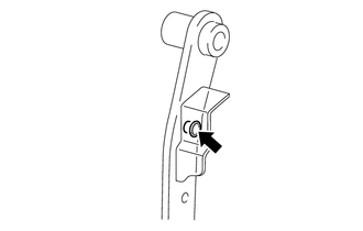
INSTALL CLUTCH PEDAL STOPPER
-
Install the clutch pedal stopper to the clutch pedal sub-assembly.
-
-
INSTALL NO. 1 CLUTCH PEDAL CUSHION
-
Install the No. 1 clutch pedal cushion to the clutch pedal sub-assembly.
-
-
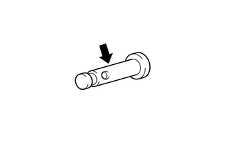
INSTALL CLUTCH MASTER CYLINDER PUSH ROD CLEVIS BUSH
-
Install a new clutch master cylinder push rod clevis bush to the clutch pedal sub-assembly.
Tech Tips
Install the clutch master cylinder push rod clevis bush from the right side of the vehicle.
-
Apply MP grease to the inside of the clutch master cylinder push rod clevis bush.
Text in Illustration 
MP grease
-
-
INSTALL CLUTCH PEDAL SHAFT COLLAR
-
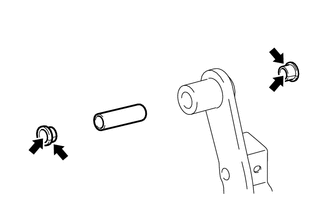
Apply MP grease to both sides of 2 new clutch pedal bushes.
Text in Illustration MP grease -
Install the 2 clutch pedal bushes and the clutch pedal shaft collar to the clutch pedal sub-assembly.
-
-
INSTALL CLUTCH PEDAL SUB-ASSEMBLY
-
Install the clutch pedal sub-assembly to the clutch pedal support sub-assembly with the bolt and the nut.
- Torque:
- 37 N*m { 375 kgf*cm, 27 ft.*lbf }
Note
Turn the nut while holding the bolt.
-
-
INSTALL CLUTCH PEDAL SPRING (except 1ND-TV)
-
Install the clutch pedal spring to the clutch pedal sub-assembly and the clutch pedal support sub-assembly.
-
-
INSTALL CLUTCH PEDAL SPRING HOLDER (for 1ND-TV)
-
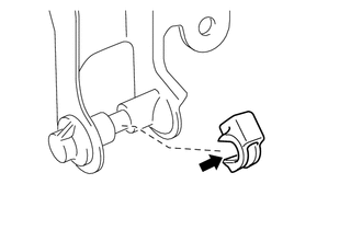
Apply MP grease to the contact surface of the clutch pedal spring holder and the clutch pedal support sub-assembly.
Text in Illustration MP grease -
Install the clutch pedal spring holder to the clutch pedal support sub-assembly.
-
-
INSTALL CLUTCH PEDAL TURNOVER BUSH (for 1ND-TV)
-
Install a new clutch pedal turnover bush to the clutch pedal sub-assembly.
-
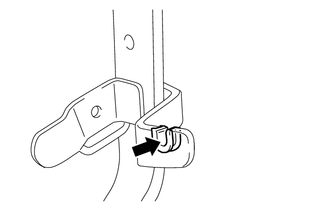
Apply MP grease to the contact surface of the clutch pedal turnover bush and the pedal spring.
Text in Illustration MP grease
-
-
INSTALL PEDAL SPRING (for 1ND-TV)
-
While the clutch pedal is fully depressed, install the pedal spring.
-
-
INSTALL CLUTCH PEDAL STOPPER BOLT
-
Install the clutch pedal stopper bolt to the clutch pedal support sub-assembly and temporarily tighten the lock nut.
Tech Tips
Tighten the lock nut to the specified torque when adjusting the clutch pedal.
-
-
INSTALL NO. 2 CLUTCH START SWITCH ASSEMBLY
-
Install the No. 2 clutch start switch assembly to the clutch pedal support sub-assembly with the nut.
- Torque:
- 16 N*m { 160 kgf*cm, 12 ft.*lbf }
-
-
INSTALL CLUTCH START SWITCH ASSEMBLY
-
Install the clutch start switch assembly to the clutch pedal support sub-assembly with the nut.
- Torque:
- 16 N*m { 160 kgf*cm, 12 ft.*lbf }
-
-
INSTALL CLUTCH PEDAL SUPPORT SUB-ASSEMBLY
-
Install the clutch pedal support sub-assembly to the vehicle with the 2 nuts.
- Torque:
- 9.0 N*m { 92 kgf*cm, 80 in.*lbf }
-
Install the 2 bolts to the clutch pedal support sub-assembly.
- Torque:
- 9.0 N*m { 92 kgf*cm, 80 in.*lbf }
-
Apply MP grease to the clevis pin.
Text in Illustration MP grease -
Install the clutch master cylinder push rod clevis to the clutch pedal sub-assembly with the clevis pin and a new clip.
Tech Tips
Install the clevis pin from the right side of the vehicle.
-
Connect the connectors and engage the wire harness clamps.
-
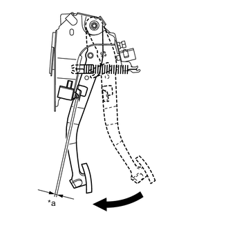
Text in Illustration *a Clearance Fully depressed With the clutch pedal fully depressed, check that the clearance shown in the illustration is as specified.
Standard clearance 2.5 to 5.5 mm (0.098 to 0.217 in.)
-
-
INSPECT AND ADJUST CLUTCH PEDAL
-
INSPECT NO. 2 CLUTCH START SWITCH ASSEMBLY
-
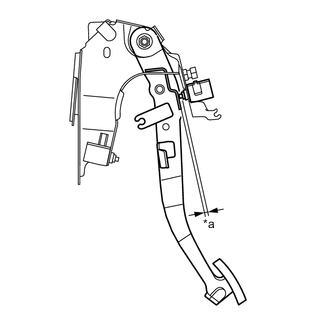
Text in Illustration *a Clearance Without depressing the clutch pedal, check that the clearance shown in the illustration is as specified.
Standard clearance for TMC Made 2.5 to 5.5 mm (0.098 to 0.217 in.) for TMMF Made except 1ND-TV 1.3 to 4.3 mm (0.051 to 0.169 in.) for TMMF Made 1ND-TV 0.5 to 3.5 mm (0.020 to 0.138 in.)
-
-
INSTALL LOWER INSTRUMENT PANEL FINISH PANEL (w/o Knee Airbag)
-
INSTALL LOWER NO. 1 INSTRUMENT PANEL AIRBAG ASSEMBLY (w/ Knee Airbag)
Tech Tips
Use the same procedure as for LHD models Click here.
-
INSTALL NO. 1 INSTRUMENT PANEL UNDER COVER SUB-ASSEMBLY
Tech Tips
Use the same procedure as for LHD models Click here.
-
INSPECT CLUTCH START SYSTEM