CLUTCH PEDAL(for LHD) INSTALLATION
PROCEDURE
-
INSTALL CLUTCH PEDAL PAD
-
Install the clutch pedal pad to the clutch pedal sub-assembly.
-
-
INSTALL NO. 1 CLUTCH PEDAL CUSHION
-
Install the No. 1 clutch pedal cushion to the clutch pedal sub-assembly.
-
-
INSTALL CLUTCH PEDAL SHAFT COLLAR
-
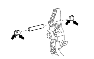
Apply MP grease to both sides of 2 new clutch pedal bushes.
Text in Illustration 
MP grease -
Install the 2 clutch pedal bushes and clutch pedal shaft collar to the clutch pedal sub-assembly.
-
-
INSTALL CLUTCH PEDAL SUB-ASSEMBLY
-
Install the clutch pedal sub-assembly to the clutch pedal support sub-assembly with the bolt and the nut.
- Torque:
- 37 N*m { 375 kgf*cm, 27 ft.*lbf }
Note
Turn the nut while holding the bolt.
-
-
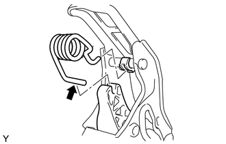
INSTALL CLUTCH PEDAL SPRING (except 1ND-TV)
-
Install the clutch pedal spring to the clutch pedal sub-assembly and the clutch pedal support sub-assembly.
-
-
INSTALL CLUTCH PEDAL SPRING HOLDER (for 1ND-TV)
-
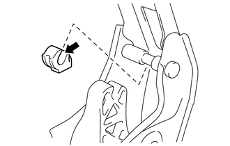
Apply MP grease to the contact surface of the clutch pedal spring holder and the clutch pedal support sub-assembly.
Text in Illustration MP grease -
Install the clutch pedal spring holder to the clutch pedal support sub-assembly.
-
-
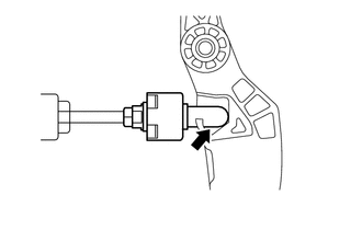
INSTALL PEDAL SPRING (for 1ND-TV)
-
Apply MP grease to the contact surface of the pedal spring and the clutch pedal sub-assembly.
Text in Illustration MP grease -
While the clutch pedal is fully depressed, install the pedal spring.
-
-
INSTALL NO. 2 CLUTCH START SWITCH ASSEMBLY
-
Install the No. 2 clutch start switch assembly to the clutch pedal support sub-assembly and temporarily tighten the lock nut.
Tech Tips
Tighten the lock nut to the specified torque when adjusting the clutch pedal.
-
-
INSTALL CLUTCH START SWITCH ASSEMBLY
-
Install the clutch start switch assembly to the clutch pedal support sub-assembly with the nut.
- Torque:
- 16 N*m { 160 kgf*cm, 12 ft.*lbf }
-
-
INSTALL CLUTCH PEDAL SUPPORT SUB-ASSEMBLY
-
Apply MP grease to the contact surface of the clutch master cylinder push rod clevis and the clutch pedal sub-assembly.
Text in Illustration MP grease -
Install the clutch master cylinder push rod clevis to the cutout of the clutch pedal sub-assembly from the left side of the vehicle and push it downward.
-
Install the clutch pedal support sub-assembly to the vehicle with the bolt and the 2 nuts.
- Torque:
- for Bolt
- 24 N*m { 241 kgf*cm, 17 ft.*lbf }
- for Nut
- 9.0 N*m { 92 kgf*cm, 80 in.*lbf }
-
Connect the connectors and engage the wire harness clamps.
-
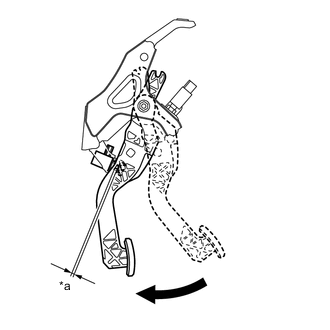
Text in Illustration *a Clearance Fully depressed With the clutch pedal fully depressed, check that the clearance shown in the illustration is as specified.
Standard clearance except 1ND-TV 2.0 to 5.0 mm (0.079 to 0.197 in.) for 1ND-TV 2.5 to 5.5 mm (0.098 to 0.217 in.)
-
-
INSPECT AND ADJUST CLUTCH PEDAL
-
INSTALL COMBINATION METER ASSEMBLY
-
INSTALL LOWER INSTRUMENT PANEL FINISH PANEL (w/o Knee Airbag)
-
INSTALL LOWER NO. 1 INSTRUMENT PANEL AIRBAG ASSEMBLY (w/ Knee Airbag)
-
INSTALL LOWER NO. 2 INSTRUMENT PANEL FINISH PANEL
-
INSTALL NO. 1 INSTRUMENT PANEL UNDER COVER SUB-ASSEMBLY
-
INSPECT CLUTCH START SYSTEM