STOP AND START SYSTEM Cooler Thermistor Circuit
DESCRIPTION
Stop and Start system control may be prohibited due to air conditioning system operation conditions. The prohibition conditions are shown in the table below.
| Prohibition Condition | Effect without Restart | Restoration Condition | Prohibition Condition Check Timing |
|---|---|---|---|
| Heater: All of the following conditions have been met:
|
Heater function is not effective |
|
During heater operation |
| Cooling function: All of the following conditions have been met:
|
Cooling function is not effective | Any of the following conditions have been met
|
While A/C (cooling function) is on |
| Defogger: All of the following conditions have been met:
|
Windows are easily fogged | The corresponding condition has been met:
|
While A/C (cooling function for defogger) is on |
WIRING DIAGRAM
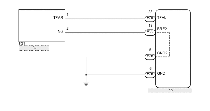
| *a | Cooler Thermistor |
| *b | Engine Stop and Start ECU |
PROCEDURE
-
READ VALUE USING INTELLIGENT TESTER (A/C OUTLET TEMP)
-
Connect the intelligent tester to the DLC3.
-
Turn the ignition switch to ON.
-
Turn the tester on.
-
Enter the following menus: Powertrain / Stop and Start / Data List / A/C Outlet Temp.
-
Read the value when the A/C temperature switch is operated (HOT to COOL).
OK Tester display value changes when the A/C switch is operated. Tech Tips
The A/C Outlet Temp item in the Data List indicates the A/C blower temperature. Leaving the vehicle for an entire day allows the A/C Outlet Temperature value to equal the ambient temperature. While the ambient temperature is indicated in the Data List, check for changes in the outlet temperature by hand. If temperature changes cannot be felt, inspect the air conditioning system.
OK 
PROCEED TO NEXT SUSPECTED AREA SHOWN IN PROBLEM SYMPTOMS TABLE Click here
NG 
-
-
INSPECT COOLER THERMISTOR
-
Inspect the cooler thermistor Click here.
NG
REPLACE COOLER THERMISTOR Click here
OK
-
-
CHECK HARNESS AND CONNECTOR (ENGINE STOP AND START ECU - COOLER THERMISTOR)
-
Disconnect the F31 cooler thermistor connector.
-
Disconnect the A53 and F75 engine stop and start ECU connector.
-
Measure the resistance according to the value(s) in the table below.
Standard Resistance Tester Connection Condition Specified Condition F75-23 (TFAL) - F31-1 (TFAR) Always Below 1 Ω A53-19 (BRE2) - F31-2 (SG) Always Below 1 Ω F31-1 (TFAR) or F75-23 (TFAL) - Body ground Always 10 kΩ or higher F31-2 (SG) or A53-19 (BRE2) - Body ground Always 10 kΩ or higher -
Reconnect the F31 cooler thermistor connector.
-
Reconnect the A53 engine stop and start ECU connector.
NG
REPAIR OR REPLACE HARNESS OR CONNECTOR
OK
-
-
CHECK HARNESS AND CONNECTOR (ENGINE STOP AND START ECU - BODY GROUND)
-
Measure the resistance according to the value(s) in the table below.
Standard Resistance Tester Connection Condition Specified Condition F75-6 (GND) - Body ground Always Below 1 Ω F75-5 (GND2) - Body ground Always Below 1 Ω -
Reconnect the F75 engine stop and start ECU connector.
OK
PROCEED TO NEXT SUSPECTED AREA SHOWN IN PROBLEM SYMPTOMS TABLE Click here
NG
REPAIR OR REPLACE HARNESS OR CONNECTOR
-