STOP AND START SYSTEM Neutral Position Switch Circuit
DESCRIPTION
The neutral position switch detects whether the shift lever is in neutral. While the neutral position switch is off, engine restart operation due to stop and start system control is prohibited.
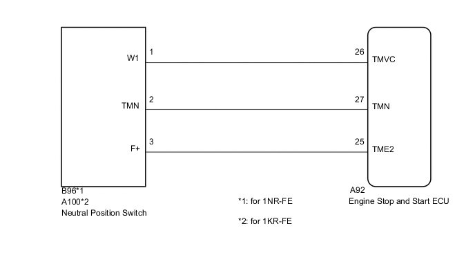
WIRING DIAGRAM
PROCEDURE
-
READ VALUE USING GTS (NEUTRAL SWITCH)
-
Connect the GTS to the DLC3.
-
Turn the ignition switch to ON.
-
Turn the GTS on.
-
Enter the following menus: Powertrain / Stop and Start / Data List / Neutral Switch.
-
Read the value when the shift lever is in neutral and any other position.
OK ON is displayed when the shift lever is in neutral. OFF is displayed when the shift lever is in any other position.
OK 
PROCEED TO NEXT SUSPECTED AREA SHOWN IN PROBLEM SYMPTOMS TABLE Click here
NG 
-
-
CHECK HARNESS AND CONNECTOR (ENGINE STOP AND START ECU - NEUTRAL POSITION SWITCH)
-
Disconnect the B96 neutral position switch connector. (for 1NR-FE)
-
Disconnect the A100 neutral position switch connector. (for 1KR-FE)
-
Disconnect the A92 engine stop and start ECU connector.
-
Measure the resistance according to the value(s) in the table below.
Standard Resistance for 1NR-FE Tester Connection Condition Specified Condition A92-26 (TMVC) - B96-1 (W1) Always Below 1 Ω A92-27 (TMN) - B96-2 (TMN) Always Below 1 Ω A92-25 (TME2) - B96-3 (F+) Always Below 1 Ω A92-26 (TMVC) or B96-1 (W1) - Body ground Always 10 kΩ or higher A92-27 (TMN) or B96-2 (TMN) - Body ground Always 10 kΩ or higher A92-25 (TME2) or B96-3 (F+) - Body ground Always 10 kΩ or higher for 1KR-FE Tester Connection Condition Specified Condition A92-26 (TMVC) - A100-1 (W1) Always Below 1 Ω A92-27 (TMN) - A100-2 (TMN) Always Below 1 Ω A92-25 (TME2) - A100-3 (F+) Always Below 1 Ω A92-26 (TMVC) or A100-1 (W1) - Body ground Always 10 kΩ or higher A92-27 (TMN) or A100-2 (TMN) - Body ground Always 10 kΩ or higher A92-25 (TME2) or A100-3 (F+) - Body ground Always 10 kΩ or higher
NG
REPAIR OR REPLACE HARNESS OR CONNECTOR
OK
-
-
CHECK NEUTRAL POSITION SWITCH (TMN TERMINAL VOLTAGE)
-
Measure the voltage according to the value(s) in the table below.
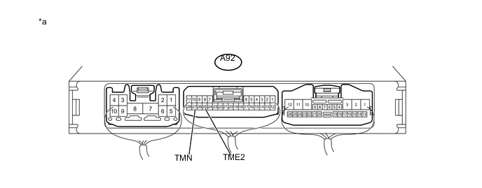
Text in Illustration *a Component with harness connected
(Engine Stop and Start ECU)
- - Standard Voltage Tester Connection Condition Specified Condition A92-27 (TMN) - A92-25 (TME2) Ignition switch ON, shift lever in neutral 2.7 to 4.3 V Ignition switch ON, shift lever in any position other than neutral 0.7 to 1.9 V Result Result Proceed to OK A NG (for 1NR-FE) B NG (for 1KR-FE) C
A
PROCEED TO NEXT SUSPECTED AREA SHOWN IN PROBLEM SYMPTOMS TABLE Click here
B
REPLACE NEUTRAL POSITION SWITCH Click here
C
REPLACE NEUTRAL POSITION SWITCH Click here
-