STOP AND START SYSTEM Backup Boost Converter Circuit
DESCRIPTION
The backup boost converter (eco run vehicle converter assembly) supplements battery voltage to help prevent it from dropping when the engine is restarted during Stop and Start system control Click here. This is done to prevent some electrical systems, such as the audio system, from being disabled due to low power supply voltage.
If any DTCs are output, troubleshoot for those DTCs first Click here.
Tech Tips
-
The backup boost converter (eco run vehicle converter assembly) has a control circuit and internal relay for each electrical system it supplies, such as the meter, audio, and air conditioning systems. If a malfunction occurs in a circuit supplied by the backup boost converter (eco run vehicle converter assembly), the relay opens and power supply to the applicable circuit will be shut off (remains open until the next trip).
Turning the ignition switch off resets the internal relays. However, they will open again when the ignition switch is turned to ON if the malfunction in the circuit has not been repaired.
The backup boost converter (eco run vehicle converter assembly) supplies power to the body ECU, steering sensor, ABS/VSC ECU, EPS ECU, meter and audio systems. If power is not supplied to any of these electrical systems, perform troubleshooting by referring to the table below.
-
For more information on the effect of malfunction on Stop and Start system operation, refer to the System Description Click here.
WIRING DIAGRAM
Refer to P323B Click here.
CAUTION / NOTICE / HINT
Note
Inspect the fuses for circuits related to this system before performing the following inspection procedure.
PROCEDURE
-
CHECK PROBLEM SYMPTOM
-
Determine the trouble area by referring to the table below.
Effect on Vehicle Trouble Area/Cause Fail-safe DTC Output Stop and start cancel indicator light Proceed to Symptom When the engine is restarted due to Stop and Start system control (Effect might not occur)
-
The audio is reset
-
The combination meter assembly fades in and out
-
EPS*1: While restarting, the steering feel is heavy
For *1, DTC might be stored
Converter internal malfunction
-
Voltage of the control IC power source within the backup boost converter (eco run vehicle converter assembly) decreases
-
Voltage of the control IC power source within the backup boost converter (eco run vehicle converter assembly) is too high
-
Inappropriate DON2 duty value is detected
-
DON2 duty cycle deviates beyond the allowable range
Stop and Start system control prohibited P323B Blinks A Backup boost converter (Eco run vehicle converter assembly) output voltage cannot be increased when the engine is restarted due to Stop and Start system control External converter malfunction
-
Open in DON2 communication line
-
Short in DON2 communication line
-
Short to GND in DON2 communication line
Battery voltage drop Depending on the type of relay that interrupts power supply
BO1, ACO: The audio will not function
BO2: Malfunction of the electric oil pump in the CVT system
IGO1: All of the following do not operate
-
Skid control system (ABS/VSC)
-
EPS (power steering)
-
Systems whose power is supplied from the main body ECU
IGO2: The combination meter assembly will not function
A relay in the converter for one of the connected systems opens and the power supply is interrupted
(occurs when overcurrent is detected for the respective system circuit)
Stop and Start system control might be prohibited (Depending on the type of component that interrupts the power supply from the backup boost converter (eco run vehicle converter assembly), or depending on if DTC is stored by ECU.) - Not illuminated
(May blink to indicate a malfunction in CAN communication)
B Any system that the backup boost converter (eco run vehicle converter assembly) supplies with power is disabled due to its power supply being interrupted Depending on the type of the input wiring with malfunctions
IG1: All of the following do not operate
-
Skid control system (ABS/VSC)
-
EPS (power steering system)
IG2: The combination meter assembly will not function
ACC: The audio will not function
Converter harness malfunction (converter input circuits)
-
Open or short to GND in IG1 circuit
-
Open or short to GND in IG2 circuit
-
Open or short to GND in ACC circuit
Stop and Start system control prohibited - Not illuminated
(May blink to indicate a malfunction in CAN communication)
B Any system that the backup boost converter (eco run vehicle converter assembly) supplies with power is disabled due to its power supply being interrupted Depending on the relay system for the component where malfunction occurs
Audio: The audio will not function
Combination meter: The combination meter assembly will not function
All of the following do not operate (Similar symptom will occur as when IGO1 is interrupted)
-
CVT system
-
Skid control system (ABS/VSC)
-
EPS (power steering system)
-
Systems whose power is supplied from the main body ECU
Malfunction in circuit for the system that the converter supplies power
(between converter and each system)
-
Short to GND in combination meter circuit
-
A short circuit in the CVT electric oil pump circuit
-
Short to GND in power steering ECU circuit
-
Short to GND in skid control ECU circuit
-
Short to GND in steering sensor circuit
-
Short to GND in main body ECU circuit
-
Short to GND in engine stop and start ECU circuit
Relay in the converter opens interrupting the power supply to the applicable system - Not illuminated
(May blink to indicate a malfunction in CAN communication)
B Any system that the backup boost converter (eco run vehicle converter assembly) supplies with power is disabled due to its power supply being interrupted All of the following will occur
-
The audio will not function
-
Skid control system (ABS/VSC)
-
EPS (power steering system)
-
The combination meter assembly will not function
-
Open in converter fuse
-
Short to GND in converter circuit
-
Malfunction in backup boost converter (eco run vehicle converter assembly)
-
Converter connector disconnected
Stop and Start system control prohibited P323B Not illuminated (meter system disabled) A All systems powered by the backup boost converter (eco run vehicle converter assembly) (refer to Wiring Diagram) do not operate Audio is interrupted
(Stored for 1 trip)
Audio excessive volume
"Overload" is shown in the Data List when the circuit is being protected. This status can be viewed by entering the following menus: Data List / State of BBC
Relay in the converter opens interrupting the power supply to the audio system
(reset when the ignition switch is turned off)
- Not illuminated C Audio system turns off while ignition switch ON and audio system cannot be turned on.
(reset when the ignition switch is turned off)
The condition differs depending on the circuit where the +B short occurs
ACC+B short: The audio will not turn off
IG1+B short: None
IG2+B short: The combination meter assembly will not turn off
Converter harness malfunction
-
Short to +B in ACC circuit
-
Short to +B in IG1 circuit
-
Short to +B in IG2 circuit
- - Not illuminated B When the ignition switch is off, a system powered by the backup boost converter (eco run vehicle converter assembly) cannot be turned off -
A 
REPAIR OR REPLACE CIRCUITS INDICATED BY OUTPUT CODE (P323B) Click here
C 
INSPECT AUDIO SYSTEM OPERATION Click here
B 
-
-
INSPECT BACKUP BOOST CONVERTER (ECO RUN VEHICLE CONVERTER ASSEMBLY) (POWER SOURCE)
-
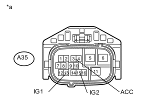
Text in Illustration *a Front view of wire harness connector:
(to Backup Boost Converter (Eco Run Vehicle Converter Assembly))
Disconnect the A35 backup boost converter (eco run vehicle converter assembly) connector.
-
Turn the ignition switch to ON.
-
Measure the voltage according to the value(s) in the table below.
Standard Voltage Tester Connection Switch Condition Specified Condition A35-3 (ACC) - Body ground Ignition switch ACC 8 to 14 V A35-13 (IG1) - Body ground Ignition switch ON 8 to 14 V A35-15 (IG2) - Body ground Ignition switch ON 8 to 14 V -
Turn the ignition switch off.
-
Measure the voltage according to the value(s) in the table below.
Standard Voltage Tester Connection Switch Condition Specified Condition A35-3 (ACC) - Body ground Ignition switch off 0 to 1 V A35-13 (IG1) - Body ground Ignition switch off 0 to 1 V A35-15 (IG2) - Body ground Ignition switch off 0 to 1 V
NG
REPAIR OR REPLACE HARNESS OR CONNECTOR
OK
-
-
CHECK HARNESS AND CONNECTOR (EACH SYSTEM - BACKUP BOOST CONVERTER (ECO RUN VEHICLE CONVERTER ASSEMBLY)
-
Disconnect the connector from the corresponding system ECU/sensor.
-
Measure the resistance according to the value(s) in the table below.
Standard Resistance (for Audio System) for TMMF Made with Navigation System Tester Connection Switch Condition Specified Condition A35-5 (BO1) - F113-4 (+B1) Always Below 1 Ω A35-12 (ACO) - F113-3 (ACC1) Always Below 1 Ω A35-5 (BO1) or F113-4 (+B1) - Body ground Always 10 kΩ or higher A35-12 (ACO) or F113-3 (ACC1) - Body ground Always 10 kΩ or higher for TMMF Made without Navigation System Tester Connection Switch Condition Specified Condition A35-5 (BO1) - F45-4 (+B1) Always Below 1 Ω A35-12 (ACO) - F45-3 (ACC1) Always Below 1 Ω A35-5 (BO1) or F45-4 (+B1) - Body ground Always 10 kΩ or higher A35-12 (ACO) or F45-3 (ACC1) - Body ground Always 10 kΩ or higher for TMC Made Tester Connection Switch Condition Specified Condition A35-5 (BO1) - F107-4 (+B1) Always Below 1 Ω A35-12 (ACO) - F107-3 (ACC1) Always Below 1 Ω A35-5 (BO1) or F107-4 (+B1) - Body ground Always 10 kΩ or higher A35-12 (ACO) or F107-3 (ACC1) - Body ground Always 10 kΩ or higher for 8 Speakers Tester Connection Switch Condition Specified Condition A35-12 (ACO) - K47-12 (ACC) Always Below 1 Ω A35-12 (ACO) or K47-12 (ACC) - Body ground Always 10 kΩ or higher Standard Resistance (for CVT (Oil pump motor)) Tester Connection Switch Condition Specified Condition A35-4 (BO2) - oil pump motor control relay terminal 5 Always Below 1 Ω A35-4 (BO2) or oil pump motor control relay terminal 5 - Body ground Always 10 kΩ or higher Standard Resistance (for VSC/ABS System) for TMMF made LHD with CVT and RHD Tester Connection Switch Condition Specified Condition A35-14 (IGO1) - A78-7 (IG1) Always Below 1 Ω A35-14 (IGO1) or A78-7 (IG1) - Body ground Always 10 kΩ or higher for TMMF made except LHD with CVT Tester Connection Switch Condition Specified Condition A35-14 (IGO1) - A79-7 (IG1) Always Below 1 Ω A35-14 (IGO1) or A79-7 (IG1) - Body ground Always 10 kΩ or higher for TMC made LHD with CVT Tester Connection Switch Condition Specified Condition A35-14 (IGO1) - A56-34 (IG1) Always Below 1 Ω A35-14 (IGO1) or A56-34 (IG1) - Body ground Always 10 kΩ or higher for TMC made except LHD with CVT Tester Connection Switch Condition Specified Condition A35-14 (IGO1) - A54-34 (IG1) Always Below 1 Ω A35-14 (IGO1) or A54-34 (IG1) - Body ground Always 10 kΩ or higher Standard Resistance (for Steering Angle Sensor) Tester Connection Switch Condition Specified Condition A35-14 (IGO1) - F30-5 (IG) Always Below 1 Ω A35-14 (IGO1) or F30-5 (IG) - Body ground Always 10 kΩ or higher Standard Resistance (for Power Steering System) Tester Connection Switch Condition Specified Condition A35-14 (IGO1) - F6-1 (IG) Always Below 1 Ω A35-14 (IGO1) or F6-1 (IG) - Body ground Always 10 kΩ or higher Standard Resistance (for Meter/Gauge System) Tester Connection Switch Condition Specified Condition A35-16 (IGO2) - F1-39 (IG+) Always Below 1 Ω A35-16 (IGO2) or F1-39 (IG+) - Body ground Always 10 kΩ or higher Standard Resistance (for Main body ECU) Tester Connection Switch Condition Specified Condition A35-16 (IGO2) - 3A-40 (IG+) Always Below 1 Ω A35-16 (IGO2) or 3A-40 (IG+) - Body ground Always 10 kΩ or higher -
Reconnect the A35 backup boost converter (eco run vehicle converter assembly) connector.
NG
REPAIR OR REPLACE HARNESS OR CONNECTOR (CORRESPONDING SYSTEM - BACKUP BOOST CONVERTER (ECO RUN VEHICLE CONVERTER ASSEMBLY))
OK
-
-
INSPECT BACKUP BOOST CONVERTER (ECO RUN VEHICLE CONVERTER ASSEMBLY) (OUTPUT VOLTAGE FOR EACH SYSTEM)
-
Turn the ignition switch to ON.
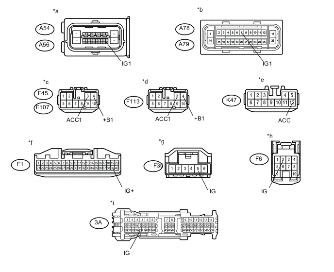
Text in Illustration *a Front view of wire harness connector:
(to Brake Actuator Assembly (Skid Control ECU for TMC Made))
*b Front view of wire harness connector:
(to Brake Actuator Assembly (Skid Control ECU for TMMF Made))
*c Front view of wire harness connector:
(to Radio Receiver Assembly for TMC Made)
*d Front view of wire harness connector:
(to Radio Receiver Assembly for TMC Made for TMMF Made)
*e Front view of wire harness connector:
(to Stereo Component Amplifier Assembly)
*f Front view of wire harness connector:
(to Combination Meter Assembly)
*g Front view of wire harness connector:
(to Steering Angle Sensor)
*h Front view of wire harness connector:
(to Power Steering ECU Assembly)
*i Front view of wire harness connector:
(to Main Body ECU (Multi Network Body ECU))
- - -
Measure the voltage according to the value(s) in the table below.
Tech Tips
Measure the voltage at the corresponding terminals.
Standard Voltage Tester Connection Switch Condition Specified Condition A56-34 (IG1)*1 - Body ground Ignition switch ON 8 to 14 V A54-34 (IG1)*2 - Body ground Ignition switch ON 8 to 14 V A78-7 (IG1)*3 - Body ground Ignition switch ON 8 to 14 V A79-7 (IG1)*4 - Body ground Ignition switch ON 8 to 14 V F113-4 (+B1)*5 - Body ground Always 8 to 14 V F45-4 (+B1)*6 - Body ground Always 8 to 14 V F107-4 (+B1)*7 - Body ground Always 8 to 14 V F113-3 (ACC1)*5 - Body ground Ignition switch ON 8 to 14 V F45-3 (ACC1)*6 - Body ground Ignition switch ON 8 to 14 V F107-3 (ACC1)*7 - Body ground Ignition switch ON 8 to 14 V K47-12 (ACC)*8 - Body ground Ignition switch ON 8 to 14 V F1-39 (IG+) - Body ground Ignition switch ON 8 to 14 V F30-5 (IG) - Body ground Ignition switch ON 8 to 14 V F6-1 (IG) - Body ground Ignition switch ON 8 to 14 V 3A-40 (IG) - Body ground Ignition switch ON 8 to 14 V *1: for TMMF Made LHD with CVT and RHD
*2: for TMMF Made except LHD with CVT
*3: for TMC Made LHD with CVT
*4: for TMC Made except LHD with CVT
*5: for TMMF Made with Navigation System
*6: for TMMF Made without Navigation System
*7: for TMC Made
*8: for 8 Speakers
-
Reconnect the connector to the corresponding system ECU/sensor.
OK
INSPECT POWER SOURCE CIRCUIT OF CORRESPONDING SYSTEM
NG
REPLACE BACKUP BOOST CONVERTER (ECO RUN VEHICLE CONVERTER ASSEMBLY) Click here
-
-
INSPECT AUDIO SYSTEM OPERATION
-
Turn the ignition switch off and wait for 1 minute.
-
Turn the ignition switch to ON.
-
Lower the audio volume.
-
Check if the audio system operates normally.
OK Audio system operates normally.
OK
END (VOLUME WAS TOO HIGH)
NG
-
-
CHECK HARNESS AND CONNECTOR (BACKUP BOOST CONVERTER (ECO RUN VEHICLE CONVERTER ASSEMBLY) - AUDIO SYSTEM)
-
Disconnect the A35 backup boost converter (eco run vehicle converter assembly) connector.
-
Disconnect the F113, F45, F107 or K47 audio system connector.
-
Measure the resistance according to the value(s) in the table below.
Standard Resistance (Check for Short) for TMMF Made with Navigation System Tester Connection Condition Specified Condition A35-5 (BO1) or F113-4 (+B1) - body ground Always 10 kΩ or higher A35-12 (ACO) or F113-3 (ACC1) - body ground Always 10 kΩ or higher for TMMF Made without Navigation System Tester Connection Condition Specified Condition A35-5 (BO1) or F45-4 (+B1) - body ground Always 10 kΩ or higher A35-12 (ACO) or F45-3 (ACC1) - body ground Always 10 kΩ or higher for TMC Made Tester Connection Switch Condition Specified Condition A35-5 (BO1) or F107-4 (+B1) - Body ground Always 10 kΩ or higher A35-12 (ACO) or F107-3 (ACC1) - Body ground Always 10 kΩ or higher for 8 Speakers Tester Connection Switch Condition Specified Condition A35-12 (ACO) or K47-12 (ACC) - Body ground Always 10 kΩ or higher -
Reconnect the A35 backup boost converter (eco run vehicle converter assembly) connector.
-
Reconnect the audio system connector.
OK
CHECK AUDIO SYSTEM (POWER SOURCE CIRCUIT)
NG
REPAIR OR REPLACE HARNESS OR CONNECTOR
-