STOP AND START SYSTEM Starter Signal Circuit
DESCRIPTION
By using the starter delay circuit, the engine stop and start ECU can activate the ST NO. 2 relay (for starter motor operation) after activating the ST relay (for starter pinion operation) to operate the starter assembly.
WIRING DIAGRAM
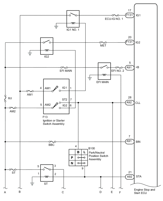
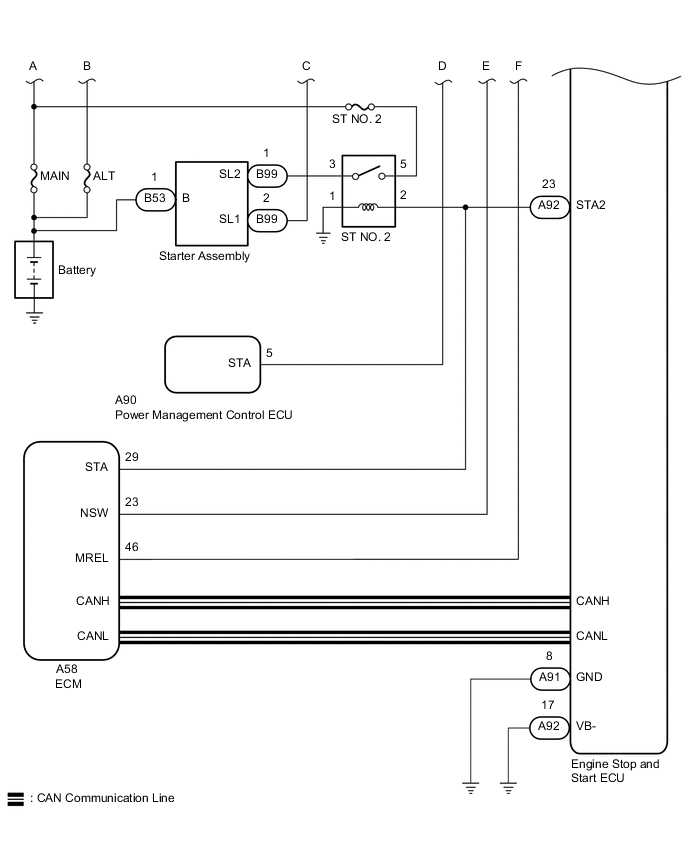
CAUTION / NOTICE / HINT
Note
-
Before replacing the engine stop and start ECU, read the number of starter operations and write it into a new engine stop and start ECU Click here.
-
After replacing the engine stop and start ECU or air conditioning control assembly, reset and perform learning of the air conditioning information in the engine stop and start ECU Click here.
-
After replacing the engine stop and start ECU or airbag sensor assembly, clear and calibrate the deceleration sensor zero point in the engine stop and start ECU Click here.
-
After replacing the starter assembly, perform initialization of the number of starter operations stored in the engine stop and start ECU Click here
-
When the starter assembly is replaced, "ST relay" and "ST NO. 2 relay" must be also replaced.
-
Inspect the fuses for circuits related to this system before performing the following inspection procedure.
Tech Tips
Using the GTS, read the freeze frame data before troubleshooting. System condition information is recorded as freeze frame data the moment a DTC is stored. This information can be useful when troubleshooting Click here.
PROCEDURE
-
CHECK CRANKING OPERATION
-
Turn the ignition switch to ON and check that the engine cranks.
Result Result Proceed to The engine cranks A The engine does not crank B
B 
PERFORM ACTIVE TEST USING GTS (STARTER) Click here
A 
-
-
PERFORM ACTIVE TEST USING GTS (STARTER)
-
Connect the GTS to the DLC3.
-
Turn the ignition switch to ON.
-
Turn the GTS on.
-
Enter the following menus: Powertrain / Stop and Start / Active Test / Starter.
-
Check whether the engine cranks while the Active Test "Starter" is being performed.
Note
The Active Test "Starter" is stopped automatically 3 seconds after the starter assembly begins operating.
OK The engine cranks
OK 
GO TO DTC P1603 (CONFIRM CAUSE OF ENGINE STALL)) Click here
NG
-
-
CHECK HARNESS AND CONNECTOR (ENGINE STOP AND START ECU)
-
Disconnect the engine stop and start ECU connectors.
-
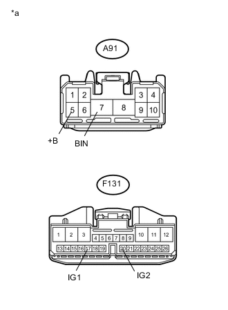
Text in Illustration *a Front view of wire harness connector
(to Engine Stop and Start ECU)
Measure the voltage according to the value(s) in the table below.
Standard Voltage Tester Connection Condition Specified Condition A91-7 (BIN) - Body ground Always 9.5 to 14 V -
Turn the ignition switch to ON.
-
Measure the voltage according to the value(s) in the table below.
Standard Voltage Tester Connection Switch Condition Specified Condition A91-5 (+B) - Body ground Ignition switch ON 9.5 to 14 V F131-17 (IG1) - Body ground Ignition switch ON 9.5 to 14 V F131-20 (IG2) - Body ground Ignition switch ON 9.5 to 14 V
NG
REPAIR OR REPLACE HARNESS AND CONNECTOR
OK
-
-
CHECK HARNESS AND CONNECTOR (ENGINE STOP AND START ECU - BODY GROUND)
-
Disconnect the A91 and A92 engine stop and start ECU connectors.
-
Measure the resistance according to the value(s) in the table below.
Standard Resistance Tester Connection Condition Specified Condition A91-8 (GND) - Body ground Always Below 1 Ω A92-17 (VB-) - Body ground Always Below 1 Ω
OK
GO TO DTC P1603 (CONFIRM CAUSE OF ENGINE STALL)) Click here
NG
REPAIR OR REPLACE HARNESS AND CONNECTOR
-
-
PERFORM ACTIVE TEST USING GTS (STARTER)
-
Connect the GTS to the DLC3.
-
Turn the ignition switch to ON.
-
Turn the GTS on.
-
Enter the following menus: Powertrain / Stop and Start / Active Test / Starter.
-
Check whether the engine cranks while the Active Test "Starter" is being performed.
Note
The Active Test "Starter" is stopped automatically 3 seconds after the starter assembly begins operating.
OK The engine cranks
NG
INSPECT ENGINE STOP AND START ECU Click here
OK
-
-
READ VALUE USING GTS (NEUTRAL SWITCH)
-
Connect the GTS to the DLC3.
-
Turn the ignition switch to ON.
-
Turn the GTS on.
-
Enter the following menus: Powertrain / Stop and Start / Data List / Neutral Switch.
-
Read the Data Monitor when the shift lever is operated
OK Tester Display Measurement Item/Range Normal Condition Diagnostic Note Neutral Switch Displays the shift position N or P /
Displays ON or OFF
ON: Shift lever is in N or P
OFF: Shift lever is in other than N or P
- Result Result Proceed to Data Monitor display is not within standards A Data Monitor display is within standards B
B
INSPECT IGNITION OR STARTER SWITCH ASSEMBLY Click here
A
-
-
INSPECT PARK/NEUTRAL POSITION SWITCH
-
Inspect the park/neutral position switch Click here.
NG
REPLACE PARK/NEUTRAL POSITION SWITCH Click here
OK
-
-
CHECK HARNESS AND CONNECTOR (IGNITION OR STARTER SWITCH ASSEMBLY - PARK/NEUTRAL POSITION SWITCH)
-
Disconnect the F13 ignition or starter switch assembly connector.
-
Disconnect the A92 engine stop and start ECU connector.
-
Disconnect the A58 ECM connector.
-
Disconnect the B100 park/neutral position switch connector.
-
Measure the resistance according to the value(s) in the table below.
Standard Resistance Tester Connection Condition Specified Condition F13-7 (ST2) - B100-4 (B) Always Below 1 Ω F13-7 (ST2), B100-4 (B), A92-28 (CLL) or A58-23 (NSW) - Body ground Always 10 kΩ or higher
NG
REPAIR OR REPLACE HARNESS AND CONNECTOR
OK
-
-
CHECK HARNESS AND CONNECTOR (PARK/NEUTRAL POSITION SWITCH - ST RELAY)
-
Remove the ST relay from engine room relay block.
-
Disconnect the A92 engine stop and start ECU connector.
-
Disconnect the A90 power management control ECU connector.
-
Disconnect the B100 park/neutral position switch connector.
-
Measure the resistance according to the value(s) in the table below.
Standard Resistance Tester Connection Condition Specified Condition ST relay holder 2 - B100-9 (L) Always Below 1 Ω ST relay holder 2, B100-9 (L), A92-21 (STA) or A90-5 (STA) - Body ground Always 10 kΩ or higher
OK
PROCEED TO NEXT SUSPECTED AREA SHOWN IN PROBLEM SYMPTOMS TABLE Click here
NG
REPAIR OR REPLACE HARNESS AND CONNECTOR
-
-
INSPECT IGNITION OR STARTER SWITCH ASSEMBLY
-
Inspect the ignition or starter switch assembly Click here.
NG
REPLACE IGNITION OR STARTER SWITCH ASSEMBLY
OK
-
-
CHECK HARNESS AND CONNECTOR (IGNITION OR STARTER SWITCH ASSEMBLY - BATTERY)
-
Disconnect the ignition or starter switch assembly connector.
-
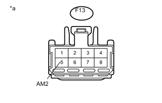
Text in Illustration *a Front view of wire harness connector
(to Ignition or Starter Switch Assembly)
Measure the voltage according to the value(s) in the table below.
Standard Voltage Tester Connection Condition Specified Condition F13-5 (AM2) - Body ground Always 9.5 to 14 V
NG
REPAIR OR REPLACE HARNESS AND CONNECTOR
OK
-
-
CHECK HARNESS AND CONNECTOR (IGNITION OR STARTER SWITCH ASSEMBLY - PARK/NEUTRAL POSITION SWITCH)
-
Disconnect the F13 ignition or starter switch assembly connector.
-
Disconnect the A92 engine stop and start ECU connector.
-
Disconnect the A58 ECM connector.
-
Disconnect the B100 park/neutral position switch connector.
-
Measure the resistance according to the value(s) in the table below.
Standard Resistance Tester Connection Condition Specified Condition F13-7 (ST2) - B100-4 (B) Always Below 1 Ω F13-7 (ST2), B100-4 (B), A92-28 (CLL) or A58-23 (NSW) - Body ground Always 10 kΩ or higher
OK
PROCEED TO NEXT SUSPECTED AREA SHOWN IN PROBLEM SYMPTOMS TABLE Click here
NG
REPAIR OR REPLACE HARNESS AND CONNECTOR
-
-
INSPECT ENGINE STOP AND START ECU
-
Connect an oscilloscope to the STA, STA2 and GND terminals of the engine stop and start ECU connector.
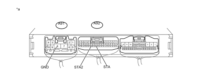
Text in Illustration *a Component with harness connected:
(Engine Stop and Start ECU)
- - -
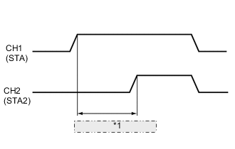
*1 0.03 to 0.06 seconds Check the waveform immediately after starting.
Item Condition Tester connection A92-21 (STA) - A91-8 (GND)
A92-21 (STA2) - A91-8 (GND)
Tool Setting 10 V/DIV., 10 ms./DIV. Condition Engine starting by operating the ignition or starter switch assembly, or pushing the push start switch Result Tester Connection Condition Specified Condition Proceed to A92-21 (STA) - A91-8 (GND)
A92-23 (STA2) - A91-8 (GND)
Engine starting by operating the ignition or starter switch assembly, or pushing the push start switch Time from ST relay on to ST2 relay on is within a 0.03 to 0.06 second frame A Time from ST relay on to ST2 relay on is not within a 0.03 to 0.06 second frame B ST relay turns on but ST2 relay remains off C Both ST relay and ST2 relay remain off D Note
After replacing the engine stop and start ECU, check that there is no malfunction in the ring gear or starter pinion. Malfunctions in the delay circuit may cause wear in the ring gear or starter pinion.
B
REPLACE ENGINE STOP AND START ECU Click here
C
CHECK HARNESS AND CONNECTOR (POWER SOURCE) Click here
D
CHECK HARNESS AND CONNECTOR (ST RELAY - BODY GROUND) Click here
A
-
-
INSPECT RELAY (ST RELAY, ST NO. 2 RELAY)
-
Inspect the ST relay Click here.
-
Inspect the ST NO. 2 relay Click here.
NG
REPLACE RELAY (ST RELAY, ST2 RELAY)
OK
-
-
CHECK HARNESS AND CONNECTOR (ST RELAY, ST NO. 2 RELAY - BATTERY)
-
w/o Pre-crash Safety City Heater
-
Remove the ST relay from engine room relay block.
-
Remove the ST NO. 2 relay from No. 2 engine room relay block.
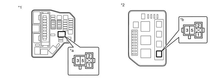
Text in Illustration *1 Engine Room Relay Block *2 No. 2 Engine Room Relay Block *a ST Relay Holder *b ST NO. 2 Relay Holder -
Remove the ST NO. 2 relay from No. 2 engine room relay block.
-
Measure the voltage according to the value(s) in the table below.
Standard Voltage Tester Connection Condition Specified Condition ST relay holder 5 - body ground Always 9.5 to 14 V ST NO. 2 relay holder 5 - body ground Always 9.5 to 14 V
-
-
w/ Pre-crash Safety City Heater
-
Remove the ST relay from engine room relay block.
-
Remove the ST NO. 2 relay from No. 2 engine room relay block.
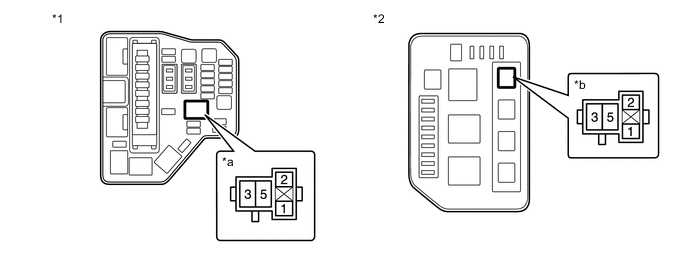
Text in Illustration *1 Engine Room Relay Block *2 No. 2 Engine Room Relay Block *a ST Relay Holder *b ST NO. 2 Relay Holder -
Remove the ST NO. 2 relay from No. 2 engine room relay block.
-
Measure the voltage according to the value(s) in the table below.
Standard Voltage Tester Connection Condition Specified Condition ST relay holder 5 - body ground Always 9.5 to 14 V ST NO. 2 relay holder 5 - body ground Always 9.5 to 14 V
-
NG
REPAIR OR REPLACE HARNESS AND CONNECTOR
OK
-
-
CHECK HARNESS AND CONNECTOR (ST RELAY, ST NO. 2 RELAY - STARTER ASSEMBLY)
-
Remove the ST relay from engine room relay block.
-
Remove the ST NO. 2 relay from No. 2 engine room relay block.
-
Disconnect the B99 starter assembly connector.
-
Measure the resistance according to the value(s) in the table below.
Standard Resistance Tester Connection Condition Specified Condition ST relay holder 3 - B99-2 (SL1) Always Below 1 Ω ST NO. 2 relay holder 3 - B99-1 (SL2) Always Below 1 Ω
NG
REPAIR OR REPLACE HARNESS AND CONNECTOR
OK
-
-
CHECK HARNESS AND CONNECTOR (ST RELAY - BODY GROUND)
-
Remove the ST relay from engine room relay block.
-
Measure the resistance according to the value(s) in the table below.
Standard Resistance Tester Connection Condition Specified Condition ST relay holder 1 - body ground Always Below 1 Ω
NG
REPAIR OR REPLACE HARNESS AND CONNECTOR
OK
-
-
CHECK HARNESS AND CONNECTOR (ST NO. 2 RELAY - BODY GROUND)
-
Remove the ST NO. 2 relay from No. 2 engine room relay block.
-
Measure the resistance according to the value(s) in the table below.
Standard Resistance Tester Connection Condition Specified Condition ST NO. 2 relay holder 1 - Body ground Always Below 1 Ω
NG
REPAIR OR REPLACE HARNESS AND CONNECTOR
OK
-
-
CHECK HARNESS AND CONNECTOR (ENGINE STOP AND START ECU - ST RELAY)
-
Disconnect the A91 and A92 engine stop and start ECU connectors.
-
Disconnect the A58 ECM connector.
-
Disconnect the A90 power management control ECU connector.
-
Disconnect the B100 park/neutral position switch connector.
-
Remove the ST relay from engine room relay block.
-
Remove the ST NO. 2 relay from No. 2 engine room relay block.
-
Remove the BBC fuse from engine room relay block and junction block assembly.
-
Measure the resistance according to the value(s) in the table below.
Standard Resistance Tester Connection Condition Specified Condition A92-21 (STA) - ST relay holder 2 Always Below 1 Ω A92-23 (STA2) - ST NO. 2 relay holder 2 Always Below 1 Ω A92-21 (STA), A90-5 (STA), B100-9 (L) or ST relay holder 2 - Body ground Always Below 1 Ω A92-23 (STA2), A58-29 (STA) or ST NO. 2 relay holder 2 - Body ground Always Below 1 Ω A91-7 (BIN) - A92-21 (STA) Always 10 kΩ or higher A91-7 (BIN) - A92-23 (STA2) Always 10 kΩ or higher
NG
REPAIR OR REPLACE HARNESS AND CONNECTOR
OK
-
-
CHECK HARNESS AND CONNECTOR (ENGINE STOP AND START ECU - ST NO. 2 RELAY)
-
Disconnect the A58 ECM connector.
-
Disconnect the A92 engine stop and start ECU.
-
Remove the ST NO. 2 relay from No. 2 engine room relay block.
-
Measure the resistance according to the value(s) in the table below.
Standard Resistance Tester Connection Condition Specified Condition A92-23 (STA2) - ST NO. 2 relay holder 2 Always Below 1 Ω A92-23 (STA2) or ST NO. 2 relay holder 2 - Body ground Always 10 kΩ or higher
NG
REPAIR OR REPLACE HARNESS AND CONNECTOR
OK
-
-
INSPECT STARTER ASSEMBLY
-
Inspect the starter assembly Click here.
OK
PROCEED TO NEXT SUSPECTED AREA SHOWN IN PROBLEM SYMPTOMS TABLE Click here
NG
REPLACE STARTER ASSEMBLY Click here
-
-
CHECK HARNESS AND CONNECTOR (POWER SOURCE)
-
Disconnect the engine stop and start ECU connectors.
-
Text in Illustration *a Front view of wire harness connector
(to Engine Stop and Start ECU)
Measure the voltage according to the value(s) in the table below.
Standard Voltage Tester Connection Condition Specified Condition A91-7 (BIN) - Body ground Always 9.5 to 14 V -
Turn the ignition switch to ON.
-
Measure the voltage according to the value(s) in the table below.
Standard Voltage Tester Connection Switch Condition Specified Condition A91-5 (+B) - Body ground Ignition switch ON 9.5 to 14 V F131-17 (IG1) - Body ground Ignition switch ON 9.5 to 14 V F131-20 (IG2) - Body ground Ignition switch ON 9.5 to 14 V
NG
REPAIR OR REPLACE HARNESS AND CONNECTOR
OK
-
-
CHECK HARNESS AND CONNECTOR (ENGINE STOP AND START ECU - BODY GROUND)
-
Disconnect the A91 and A92 engine stop and start ECU connectors.
-
Measure the resistance according to the value(s) in the table below.
Standard Resistance Tester Connection Condition Specified Condition A91-8 (GND) - Body ground Always Below 1 Ω A92-17 (VB-) - Body ground Always Below 1 Ω
OK
REPLACE ENGINE STOP AND START ECU Click here
NG
REPAIR OR REPLACE HARNESS AND CONNECTOR
-