| DTC Code | DTC Name |
|---|---|
| P1539 | AT Oil Pump |
DESCRIPTION
Refer to DTC P1538 (Click here)
| DTC No. | Freeze Frame Data * | DTC Detection Condition | Trouble Area |
|---|---|---|---|
| P1539 | O/P Signal Fixed ON | The following condition continues for 2 seconds or more (1 trip detection logic):
|
|
| O/P Signal Fixed OFF | The following condition continues for 2 seconds or more (1 trip detection logic):
|
||
| O/P No Synchro Signal | The following condition continues for 2 seconds or more (1 trip detection logic):
|
||
| O/P Motor Curr Abnormal | The following condition continues for 2 seconds or more (1 trip detection logic):
|
||
| O/P Cycle Malfunction | The following condition continues for 2 seconds or more (1 trip detection logic):
|
*: Since each information can be confirmed by freeze frame data, record the freeze frame data before deleting the diagnosis code.
CONFIRMATION DRIVING PATTERN
DTCs for the stop and start system are not cleared even if the malfunction has been repaired. After repairing the malfunction, be sure to clear the DTCs (Click here).
Click here
-
After troubleshooting, perform the following steps to recheck for DTCs and check if the stop and start system operates normally.
Tip:
-
If the cable is disconnected from the negative (-) battery terminal, stop and start control is prohibited until refresh charge is completed. After connecting the cable, drive the vehicle until refresh charge is completed and stop and start control is permitted (approximately 15 to 40 minutes).
-
Allow the engine to idle for 3 minutes after it is warmed up and check that the engine idle speed is within 50 rpm of the target idle speed.
-
Connect the GTS to the DLC3.
-
Turn the ignition switch to ON and turn the GTS on (Click here).
-
Clear the DTCs.
-
Start the engine and warm it up.
-
Drive the vehicle at 7 km/h (4.3 mph) or more.
CAUTION:When performing Confirmation Driving Pattern, obey all speed limits and traffic laws.
-
Depress the brake pedal and stop the vehicle.
-
Keep the engine stopped by stop and start control (Keep the shift lever in D).
-
Release the brake pedal with the shift lever in D to start the engine.
-
Check that no DTCs are output (Click here).
-
-
Check if the stop and start system operates normally.
Tip:If the cable is disconnected from the negative (-) battery terminal, stop and start control is prohibited until refresh charge is completed. After connecting the cable, drive the vehicle until refresh charge is completed and stop and start control is permitted (approximately 15 to 40 minutes).
-
Start the engine and warm it up.
-
Turn the air conditioning system off.
-
Drive the vehicle at 7 km/h (4.3 mph) or more.
CAUTION:When performing Confirmation Driving Pattern, obey all speed limits and traffic laws.
-
Depress the brake pedal and stop the vehicle.
-
Allow the engine to stop by stop and start control (Keep the shift lever in D).
-
Release the brake pedal with the shift lever in D to start the engine
-
CAUTION / NOTICE / HINT
-
Before replacing the engine stop and start ECU, read the number of starter operations and write it into a new engine stop and start ECU (Click here).
-
After replacing the engine stop and start ECU or air conditioning amplifier assembly, reset and perform learning of the air conditioning information in the engine stop and start ECU (Click here).
-
After replacing the engine stop and start ECU or airbag sensor assembly, clear and calibrate the deceleration sensor zero point in the engine stop and start ECU (Click here).
-
Bleed the oil pump with motor assembly (continuously variable transaxle assembly) after removing and installing the continuously variable transaxle assembly or replacing the CVT fluid (Click here).
-
If DTCs P1538 and P1539 are output simultaneously, troubleshoot for DTC P1538 first.
-
Using the GTS, read the freeze frame data before troubleshooting. System condition information is recorded as freeze frame data the moment a DTC is stored. This information can be useful when troubleshooting (Click here).
PROCEDURE
- Click here
CHECK ANY OTHER DTCS OUTPUT (IN ADDITION TO DTC P1539)
-
Connect the GTS to the DLC3.
-
Turn the ignition switch to ON.
-
Turn the GTS on.
-
Check for DTCs and read the freeze frame data.
Table 1. Result Result Proceed to DTC P1539 is output A DTCs P1538 and P1539 are output B
- AClick here
- B
GO TO DTC CHART (P1538) (Click here)
-
- Click here
CHECK FREEZE FRAME DATA
Note:The freeze frame data is cleared when DTCs are cleared. Be sure to make a note of necessary data in advance.
-
Connect the GTS to the DLC3.
-
Turn the ignition switch to ON.
-
Turn the GTS on.
-
According to the display on the GTS, select DTC P1538 and check the sets of freeze frame data (Click here).
Table 2. Result Freeze Frame Data Item Proceed to "O/P Signal Fixed ON" is ON A "O/P Signal Fixed OFF" is ON B "O/P No Synchro Signal" is ON C "O/P Motor Curr Abnormal" is ON D O/P Cycle Malfunction" is ON E
- A
REPAIR OR REPLACE ENGINE STOP AND START ECU (Click here)
- BClick here
- CClick here
- DClick here
- EClick here
-
- Click here
CHECK WAVEFORM (OPM1 TERMINAL WAVEFORM)
-
Drive the vehicle to warm up the engine and CVT fluid.
Note:The oil pump with motor assembly (continuously variable transaxle assembly) may not operate properly if the CVT fluid temperature is low. Make sure to warm up the CVT fluid before performing the Active Test. (CVT fluid temperature: 30°C (86°F) or higher).
-
Stop the engine.
-

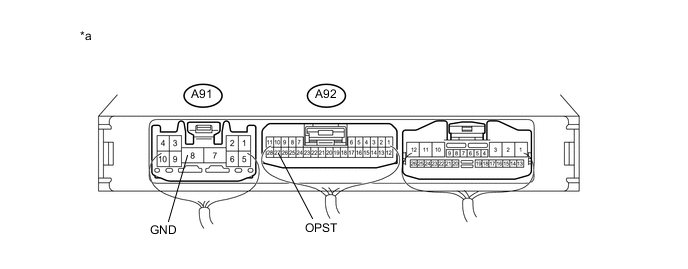
Connect an oscilloscope to terminals A92-9 (OPM1) and A91-8 (GND).
Table 3. Text In Illustration *a Component with harness connected
(Engine stop and start ECU)
- - -
Connect the GTS to the DLC3.
-
Turn the ignition switch to ON.
Tip:Do not start the engine.
-
Turn the GTS on.
-
Enter the following menus: Powertrain / Stop and Start / Active Test / AT Oil Pump (Lo).
-
Check the waveform while performing the Active Test.
Item Condition Tester Connection A92-9 (OPM1) - A91-8 (GND) Tool Setting 5 V/DIV., 5 ms./DIV. Condition
-
Turn the ignition switch to ON (engine is stopped)
-
Active Test "AT Oil Pump (Lo)" being performed
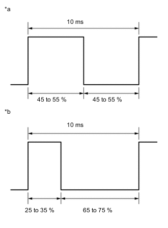
Table 4. Text In Illustration *a Normal waveform *b Abnormal waveform Standard No noise to break the waveform is detected, and the output waveform is approximately 43%. Table 5. Result Result Proceed to 38 to 48 % (Normal waveform) A There is noise in the normal waveform B 5 to 15 % (Abnormal waveform) C -
- AClick here
- B
REPAIR OR REPLACE NOISE SOURCE, HARNESS OR CONNECTOR
- C
REPAIR OR REPLACE ENGINE STOP AND START ECU (Click here)
-
- Click here
CHECK WAVEFORM (OPST TERMINAL WAVEFORM)
-
Drive the vehicle to warm up the engine and CVT fluid.
Note:The oil pump with motor assembly (continuously variable transaxle assembly) may not operate properly if the CVT fluid temperature is low. Make sure to warm up the CVT fluid before performing the Active Test. (CVT fluid temperature: 30°C (86°F) or higher).
-
Stop the engine.
-
Connect an oscilloscope to terminals A92-27 (OPST) and A91-8 (GND).
Table 6. Text In Illustration *a Component with harness connected
(Engine stop and start ECU)
- - -
Connect the GTS to the DLC3.
-
Turn the ignition switch to ON.
Tip:Do not start the engine.
-
Turn the GTS on.
-
Enter the following menus: Powertrain / Stop and Start / Active Test / AT Oil Pump (Lo).
-
Check the waveform while performing the Active Test.
Item Condition Tester Connection A92-27 (OPST) - A91-8 (GND) Tool Setting 5 V/DIV., 5 ms./DIV. Condition
-
Turn the ignition switch to ON (engine is stopped)
-
Active Test "AT Oil Pump (Lo)" being performed
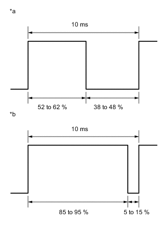
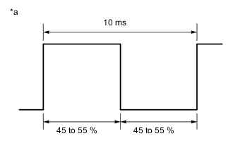
Table 7. Text In Illustration *a Normal waveform *b Abnormal waveform Standard No noise to break the waveform is detected, and the output waveform is approximately 50%. Table 8. Result Result Proceed to 65 to 75 % (Abnormal waveform) A There is noise in the normal waveform B 45 to 55% (Normal waveform) C -
- A
REPLACE OIL PUMP WITH MOTOR ASSEMBLY (Click here)
- B
REPAIR OR REPLACE NOISE SOURCE, HARNESS OR CONNECTOR
- C
REPAIR OR REPLACE ENGINE STOP AND START ECU (Click here)
-
- Click here
CHECK WAVEFORM (OPST TERMINAL WAVEFORM)
-
Drive the vehicle to warm up the engine and CVT fluid.
Note:The oil pump with motor assembly (continuously variable transaxle assembly) may not operate properly if the CVT fluid temperature is low. Make sure to warm up the CVT fluid before performing the Active Test. (CVT fluid temperature: 30°C (86°F) or higher).
-
Stop the engine.
-
Connect an oscilloscope to terminals A92-27 (OPST) and A91-8 (GND).
Table 9. Text In Illustration *a Component with harness connected
(Engine stop and start ECU)
- - -
Connect the GTS to the DLC3.
-
Turn the ignition switch to ON.
Tip:Do not start the engine.
-
Turn the GTS on.
-
Enter the following menus: Powertrain / Stop and Start / Active Test / AT Oil Pump (Lo).
-
Check the waveform while performing the Active Test.
Item Condition Tester Connection A92-27 (OPST) - A91-8 (GND) Tool Setting 5 V/DIV., 5 ms./DIV. Condition
-
Turn the ignition switch to ON (engine is stopped)
-
Active Test "AT Oil Pump (Lo)" being performed
Table 10. Text In Illustration *a Normal waveform *b Abnormal waveform Standard No noise to break the waveform is detected, and the output waveform is approximately 50%. Table 11. Result Result Proceed to 65 to 75 % (Abnormal waveform) A 45 to 55% (Normal waveform) B There is noise in the normal waveform C -
- AClick here
- BClick here
- C
REPAIR OR REPLACE NOISE SOURCE, HARNESS OR CONNECTOR
-
- Click here
READ VALUE USING GTS (A/T OIL PRESSURE (CVT OIL PRESSURE))
-
Start the engine.
-
Enter the following menus: Powertrain / Engine and ECT / Data List / A/T Oil Pressure.
-
According to the display on the GTS, read the Data List.
Standard Tester Display Measurement Item/Range Normal Condition Diagnostic Note A/T Oil Pressure Secondary oil pressure value/
min.: -64.000 MPa
max.: 64.000 MPa
0.130 to 0.450 MPa (1.3 to 4.6 kgf/cm2, 18.8 to 65.3 psi): With the shift lever in D, the engine is stopped by the start and stop system. (oil pump with motor assembly is operating) - Table 12. Result Result Proceed to Data list is within Normal Condition range A Data display is not within Normal Condition range B
- A
CHECK FOR INTERMITTENT PROBLEMS (Click here)
- B
REPLACE OIL PUMP WITH MOTOR ASSEMBLY (Click here)
-
- Click here
CHECK WAVEFORM (OPST TERMINAL WAVEFORM)
-
Drive the vehicle to warm up the engine and CVT fluid.
Note:The oil pump with motor assembly (continuously variable transaxle assembly) may not operate properly if the CVT fluid temperature is low. Make sure to warm up the CVT fluid before performing the Active Test. (CVT fluid temperature: 30°C (86°F) or higher).
-
Stop the engine.
-
Connect an oscilloscope to terminals A92-27 (OPST) and A91-8 (GND).
Table 13. Text In Illustration *a Component with harness connected
(Engine stop and start ECU)
- - -
Connect the GTS to the DLC3.
-
Turn the ignition switch to ON.
Tip:Do not start the engine.
-
Turn the GTS on.
-
Enter the following menus: Powertrain / Stop and Start / Active Test / AT Oil Pump (Lo).
-
Check the waveform while performing the Active Test.
Item Condition Tester Connection A92-27 (OPST) - A91-8 (GND) Tool Setting 5 V/DIV., 5 ms./DIV. Condition
-
Turn the ignition switch to ON (engine is stopped)
-
Active Test "AT Oil Pump (Lo)" being performed
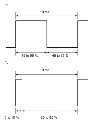
Table 14. Text In Illustration *a Normal waveform *b Abnormal waveform Standard No noise to break the waveform is detected, and the output waveform is approximately 50%. Table 15. Result Result Proceed to 85 to 95 % (Abnormal waveform) A There is noise in the normal waveform B 45 to 55% (Normal waveform) C -
- A
REPLACE OIL PUMP WITH MOTOR ASSEMBLY (Click here)
- B
REPAIR OR REPLACE NOISE SOURCE, HARNESS OR CONNECTOR
- CClick here
-
- Click here
CHECK WAVEFORM (OPST TERMINAL WAVEFORM)
-
Drive the vehicle to warm up the engine and CVT fluid.
Note:The oil pump with motor assembly (continuously variable transaxle assembly) may not operate properly if the CVT fluid temperature is low. Make sure to warm up the CVT fluid before performing the Active Test. (CVT fluid temperature: 30°C (86°F) or higher).
-
Stop the engine.
-
Connect an oscilloscope to terminals A92-27 (OPST) and A91-8 (GND).
Table 16. Text In Illustration *a Component with harness connected
(Engine stop and start ECU)
- - -
Connect the GTS to the DLC3.
-
Turn the ignition switch to ON.
Tip:Do not start the engine.
-
Turn the GTS on.
-
Enter the following menus: Powertrain / Stop and Start / Active Test / AT Oil Pump (Lo).
-
Check the waveform while performing the Active Test.
Item Condition Tester Connection A92-27 (OPST) - A91-8 (GND) Tool Setting 5 V/DIV., 5 ms./DIV. Condition
-
Turn the ignition switch to ON (engine is stopped)
-
Active Test "AT Oil Pump (Lo)" being performed
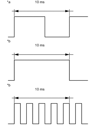
Table 17. Text In Illustration *a Normal waveform *b Abnormal waveform Standard The waveform is similar to that shown in the illustration with no noise. Table 18. Result Result Proceed to Normal waveform A There is noise in the normal waveform B Abnormal waveform (1 cycle is longer than 10 ms) C Abnormal waveform (1 cycle is shorter than 10 ms) -
- AClick here
- B
REPAIR OR REPLACE NOISE SOURCE, HARNESS OR CONNECTOR
- C
REPLACE OIL PUMP WITH MOTOR ASSEMBLY (Click here)
-
- Click here
CLEAR DTC
-
Connect the GTS to the DLC3.
-
Turn the ignition switch ON.
-
Turn the GTS on.
-
Enter the following menus: Powertrain / Stop and Start / Trouble Codes.
-
Clear the DTCs.
- NEXTClick here
-
- Click here
CHECK WAVEFORM (OPST TERMINAL WAVEFORM)
-
Drive the vehicle to warm up the engine and CVT fluid.
Note:The oil pump with motor assembly (continuously variable transaxle assembly) may not operate properly if the CVT fluid temperature is low. Make sure to warm up the CVT fluid before performing the Active Test. (CVT fluid temperature: 30°C (86°F) or higher).
-
Stop the engine.
-
Connect an oscilloscope to terminals A92-27 (OPST) and A91-8 (GND).
Table 19. Text In Illustration *a Component with harness connected
(Engine stop and start ECU)
- - -
Connect the GTS to the DLC3.
-
Turn the ignition switch to ON.
Tip:Do not start the engine.
-
Turn the GTS on.
-
Enter the following menus: Powertrain / Stop and Start / Active Test / AT Oil Pump (Lo).
-
Check the waveform while performing the Active Test.
Table 20. Text In Illustration *a Normal waveform Standard No noise to break the waveform is detected, and the output waveform is approximately 50%.
- OKClick here
- NG
REPLACE OIL PUMP WITH MOTOR ASSEMBLY (Click here)
-
- Click here
CHECK DTC OUTPUT
-
Turn the ignition switch off and wait for 30 seconds or more.
-
Turn the ignition switch to ON.
-
Start the engine.
-
Enter the following menus: Powertrain / Stop and Start / Trouble Codes.
-
Read the DTCs.
Table 21. Result Result Proceed to DTC P1539 is output A DTC P1539 is not output B Tip:If this DTC is not output again, it may have been stored when blockage temporarily prevented the oil pump with motor assembly (continuously variable transaxle assembly) from rotating.
- AClick here
- B
END
-
- Click here
READ VALUE USING GTS (A/T OIL PRESSURE (CVT OIL PRESSURE))
-
Start the engine.
-
Enter the following menus: Powertrain / Engine and ECT / Data List / A/T Oil Pressure.
-
According to the display on the GTS, read the Data List.
Standard Tester Display Measurement Item/Range Normal Condition Diagnostic Note A/T Oil Pressure Secondary oil pressure value/
min.: -64.000 MPa
max.: 64.000 MPa
0.130 to 0.450 MPa (1.3 to 4.6 kgf/cm2, 18.8 to 65.3 psi): With the shift lever in D, the engine is stopped by the start and stop system. (oil pump with motor assembly is operating) - Table 22. Result Result Proceed to Data list is within Normal Condition range A Data display is not within Normal Condition range B
- A
REPAIR OR REPLACE ENGINE STOP AND START ECU (Click here)
- B
REPLACE OIL PUMP WITH MOTOR ASSEMBLY (Click here)
-